
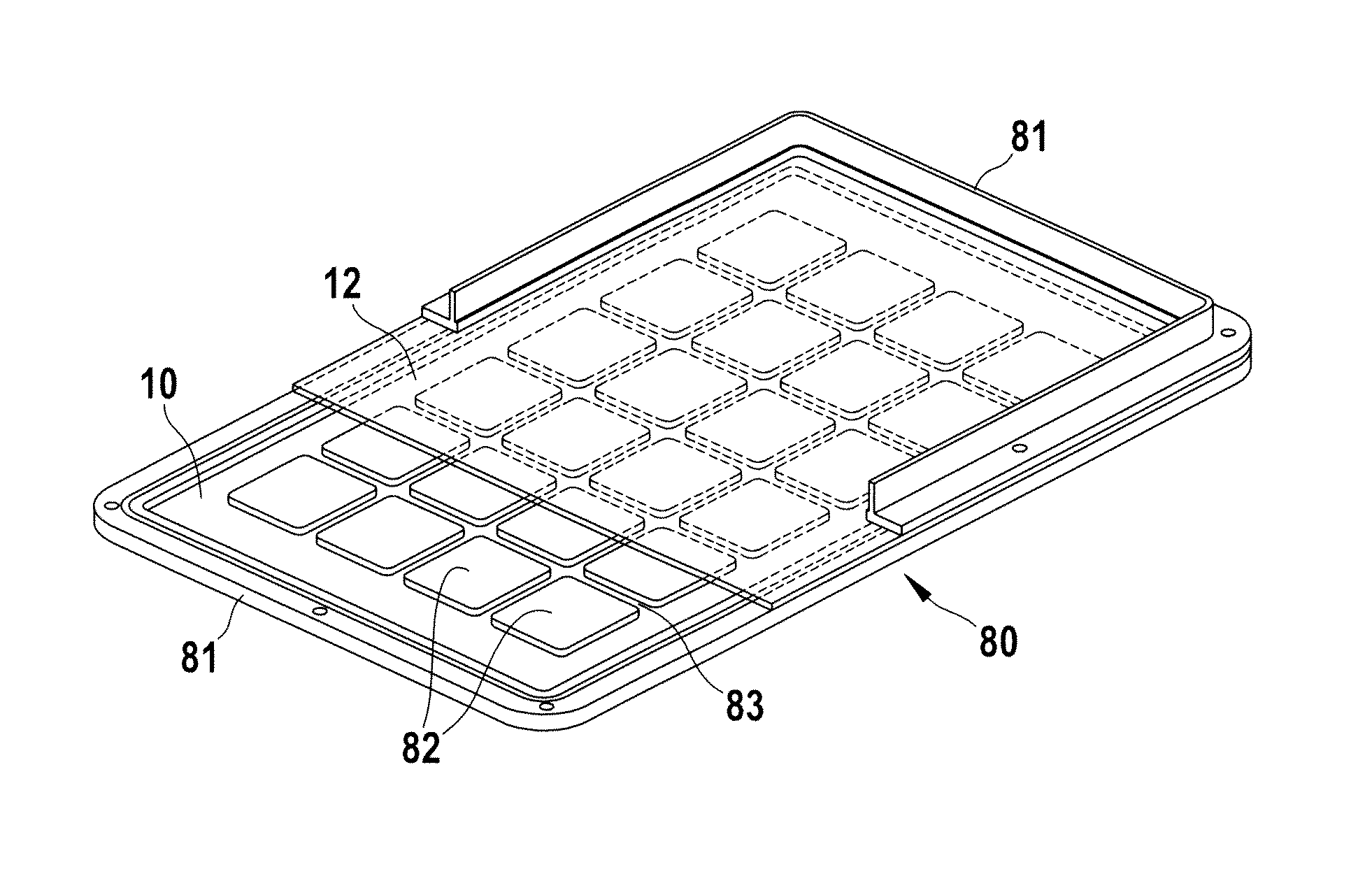
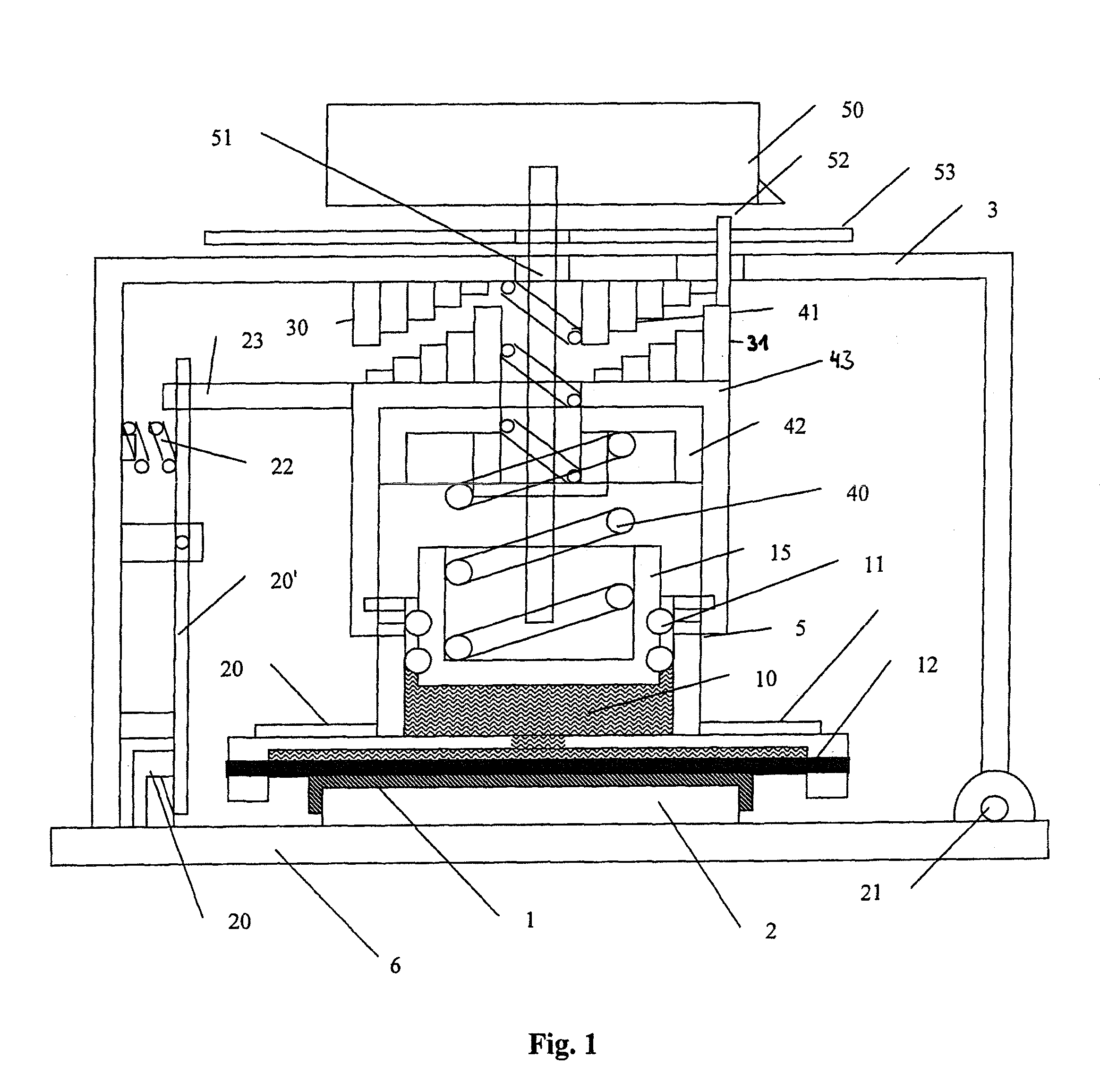
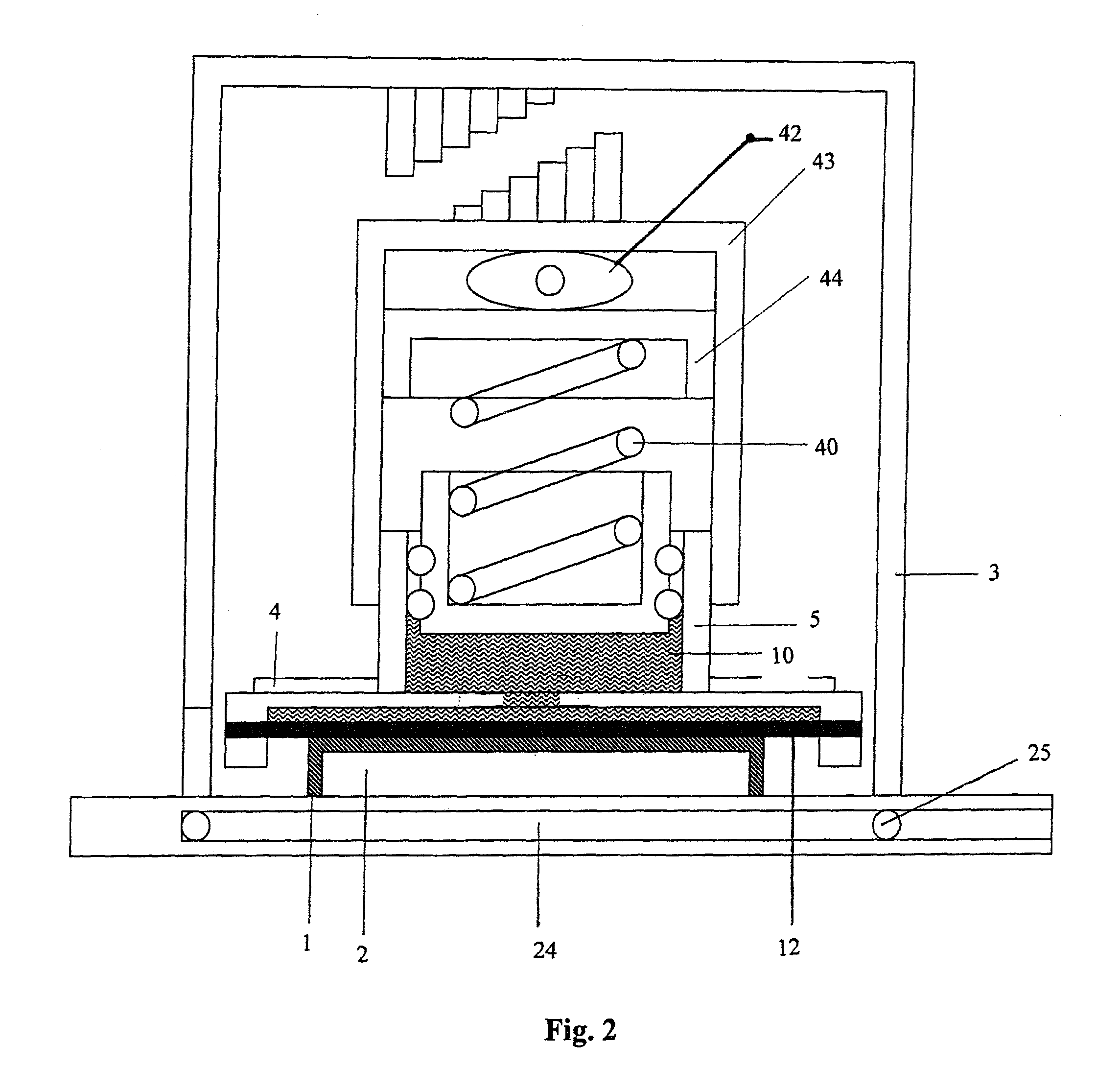
Cover for sample with homogenous pressure application

a technology of homogenous pressure and cover, which is applied in the direction of biomass after-treatment, analysis using chemical indicators, instruments, etc., can solve the problems of uneven evaporation or condensation phenomena at the different reaction sites, uneven evaporation condensation effects at the lid, and unsuitable adjustment of the rigid set-up

Active Publication Date: 2013-07-23
EPPENDORF AG
View PDF21 Cites 0 Cited by
  • Summary
  • Abstract
  • Description
  • Claims
  • Application Information

AI Technical Summary

Benefits of technology

The solution effectively prevents or minimizes evaporation and condensation across an array of reaction vessels, allowing for the use of vessels of varying heights and reducing the risk of damage to vessels and sample plates during thermal cycling.

Problems solved by technology

However, this rigid set-up is not suited to be adjusted in case reaction vessels (including caps) of different heights are present in the same array, for example due to manufacturing tolerances, since the pressure may not be evenly distributed over all wells or vessels.
Also, the set-up as described in EP '342 may lead to uneven evaporation or condensation phenomena at the different reaction sites due to uneven (inhomogeneous) application of pressure, in particular at the fringe areas of the array.
The sample arrangement of U.S. '610 also does not take into account problems associated with an uneven pressure distribution caused by the rigid plate leading to uneven evaporation condensation effects at the lid.
The teaching of WO '226, however, is restricted to a rigid heated lid and therefore leads to the very same problems in regard to uneven pressure distribution over the sample wells and therefore to (uneven) evaporation and condensation patterns, in particular at the fringes of the well plates.
WO '517 also fails to address the problem of condensation and / or uneven evaporation and condensation at the fringes of the microtiter plates.
Due to the use of a rigid plate, the same problems arise in regard to condensation and evaporation in the lid area as discussed above.

Method used


Image

  • Cover for sample with homogenous pressure application
  • Cover for sample with homogenous pressure application
  • Cover for sample with homogenous pressure application

Examples


Embodiment Construction

[0037]In accordance with the present invention, no restrictions exist in regard to the at least one sample. The sample can be a single substance, a reaction mixture or any other conceivable material. Blind samples are included.

[0038]In a preferred embodiment, the at least one sample is contained in at least on reaction vessel and / or in at least one well / dimple / indentation of a plate, in particular a sample well plate (multititer plate, PCR plate) or a block, in particular a flat block. The sample may also be contained in a consumable / disposable that is placed on a flat block.

[0039]The reaction vessel, plate or block can be disposable or can be a permanent and / or integral part of the device, in particular of the means for accommodating.

[0040]No restrictions exist in regard to the reaction vessels that optionally contain the at least one sample. In fact, it is a particular advantage of the present invention that different types of reaction vessels may be used and that even different r...


PUM

PropertyMeasurementUnit
shear modulusaaaaaaaaaa
thermal conductivityaaaaaaaaaa
thicknessaaaaaaaaaa

Abstract

The present invention relates to a cover for covering one or more sample(s) that are suitable to avoid or minimize evaporation and / or condensation of any vaporizable substance that may be present in the sample(s) or reaction mixture(s), in particular evaporation of substance at the fringes of a vessel or an array of vessels or condensation of a substance on the lid of a reaction vessel or a plate / block containing the sample(s) and / or a cover. This is achieved by providing a device comprising, among others, a force distribution unit that comprises at least one medium or material that is unable to withstand a static shear stress and deforms continuously under the action of a shear force.

Description

CROSS-REFERENCE TO RELATED APPLICATIONS[0001]This application claims the benefit under 35 U.S.C. §119(e) of U.S. Provisional Application Ser. No. 60 / 889,624 filed Feb. 13, 2007 and 35 U.S.C. §119(b) of European Patent Application 07003050.7 filed Feb. 13, 2007.FIELD OF THE INVENTION[0002]The present invention relates to a device and a method for performing processes and / or reactions that are conducted in a temperature-controlled environment.BACKGROUND OF THE INVENTION[0003]A thermal cycler for implementing chemical and / or biological reactions comprising a body for accommodating one or more reaction vessels and a cover is disclosed, for example, in EP 1 013 342. Therein, the cover for closing the base body containing the reaction vessels is rigid and is placed on top of said body. In order to seal off the reaction vessels, an electrical positioner is actuated so that a moveable part of the rigid cover is pressed against the caps of the reaction vessels. The use of a rigid cover is su...

Claims


Application Information

Patent Timeline
Patent Type & Authority Patents(United States)
IPC IPC(8): C12M1/34C12M3/00
CPCB01L7/52B01L2200/023B01L2300/046Y10T436/25B01L2300/1822B01L2300/1827B01L2300/14
Inventor LINK, HOLGERKROOG, JENS PETERTIMMANN, LUTZTASCH, HENNERKROLL, CORDULAROTH, STEFANHUHN, RUEDIGERGOETZ, REINHOLDKNOFE, HELMUTSCHAFRINSKI, ARNE
Owner EPPENDORF AG
Learn More