
Catalyst warming control-apparatus

a technology of control apparatus and catalyst, which is applied in the direction of electric propulsion mounting, machines/engines, separation processes, etc., can solve the problems of affecting the operation affecting the efficiency of the cooling control apparatus, and affecting the efficiency of the cooling system, etc., and achieves the effect of shortening the time required to enter

Inactive Publication Date: 2006-03-07
HONDA MOTOR CO LTD
View PDF23 Cites 43 Cited by
  • Summary
  • Abstract
  • Description
  • Claims
  • Application Information

AI Technical Summary

Benefits of technology

[0008]It is therefore an object of the present invention to provide a catalyst warming control apparatus which promptly warms and activates a catalyst, eliminating the catalyst heater. The hybrid vehicle may stop the engine when the engine is sufficiently warmed up, and this invention can shorten the time required to enter the state in which the engine is stopped.
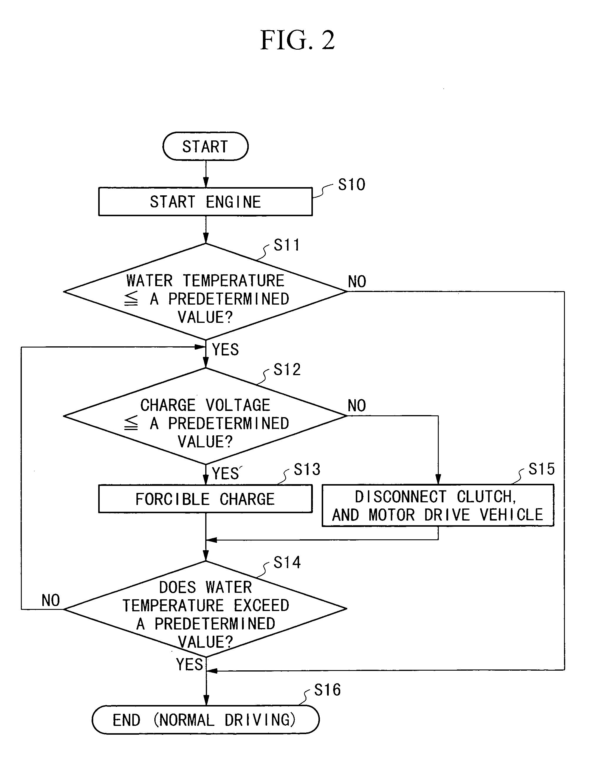
[0010]The invention of the first aspect measures the temperature of the catalyst or a value relating to the same. When the measured value is equal to or below the reference value, the generator generates electric power, and stores it in the power storage unit. This increases the load on the engine, and prompts the warm-up of the engine, so that the catalyst can be quickly activated.
[0013]This increases the load on the internal combustion engine to warm this engine, and also increases the temperature of the exhaust gas sent from the internal combustion engine, thereby warming the catalyst.
[0017]Therefore, for example, the heat produced by driving the motor increases the temperature of the cooling water. Thus, cooling of the internal combustion engine slows down because the internal combustion engine and the motor are cooled by the same cooling water, thereby shortening the time required for warming-up. Further, the load on the internal combustion engine is increased, so that the time required to warm up the internal combustion engine is shortened and the catalyst is quickly activated.

Problems solved by technology

A catalyst for cleaning exhaust gas discharged from an engine, when it is cold, is not sufficiently activated, cannot satisfactorily perform the cleaning function, and there is a problem that the exhaust gas contaminated with pollutants may be discharged to the air.
On the other hand, in the technique which includes warming the catalyst by the heater, the heater makes the exhaust system complicated and increases the size of the system.
Further, because electric power must be supplied to the heater, there is the problem that the electric power consumption of a battery is increased.

Method used


Image

  • Catalyst warming control-apparatus
  • Catalyst warming control-apparatus
  • Catalyst warming control-apparatus

Examples


Embodiment Construction

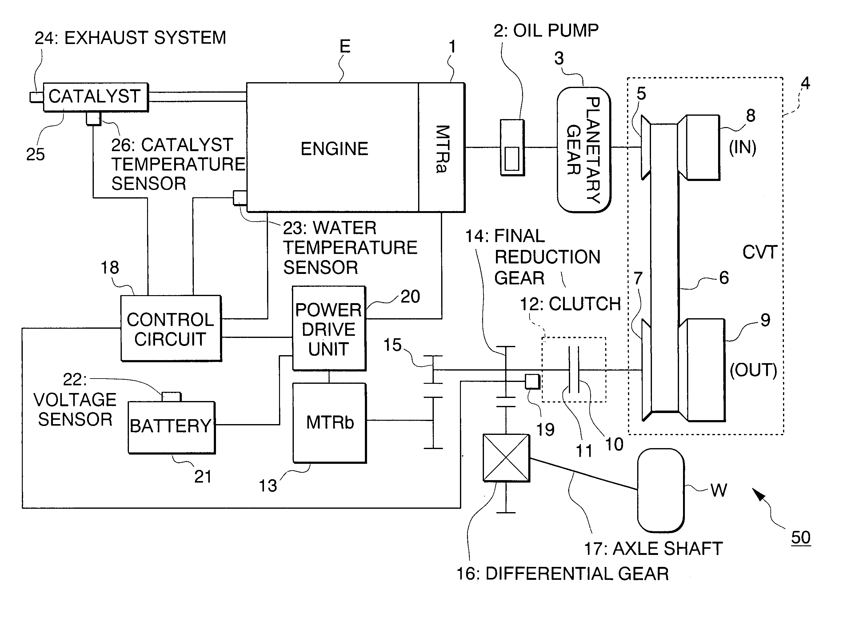
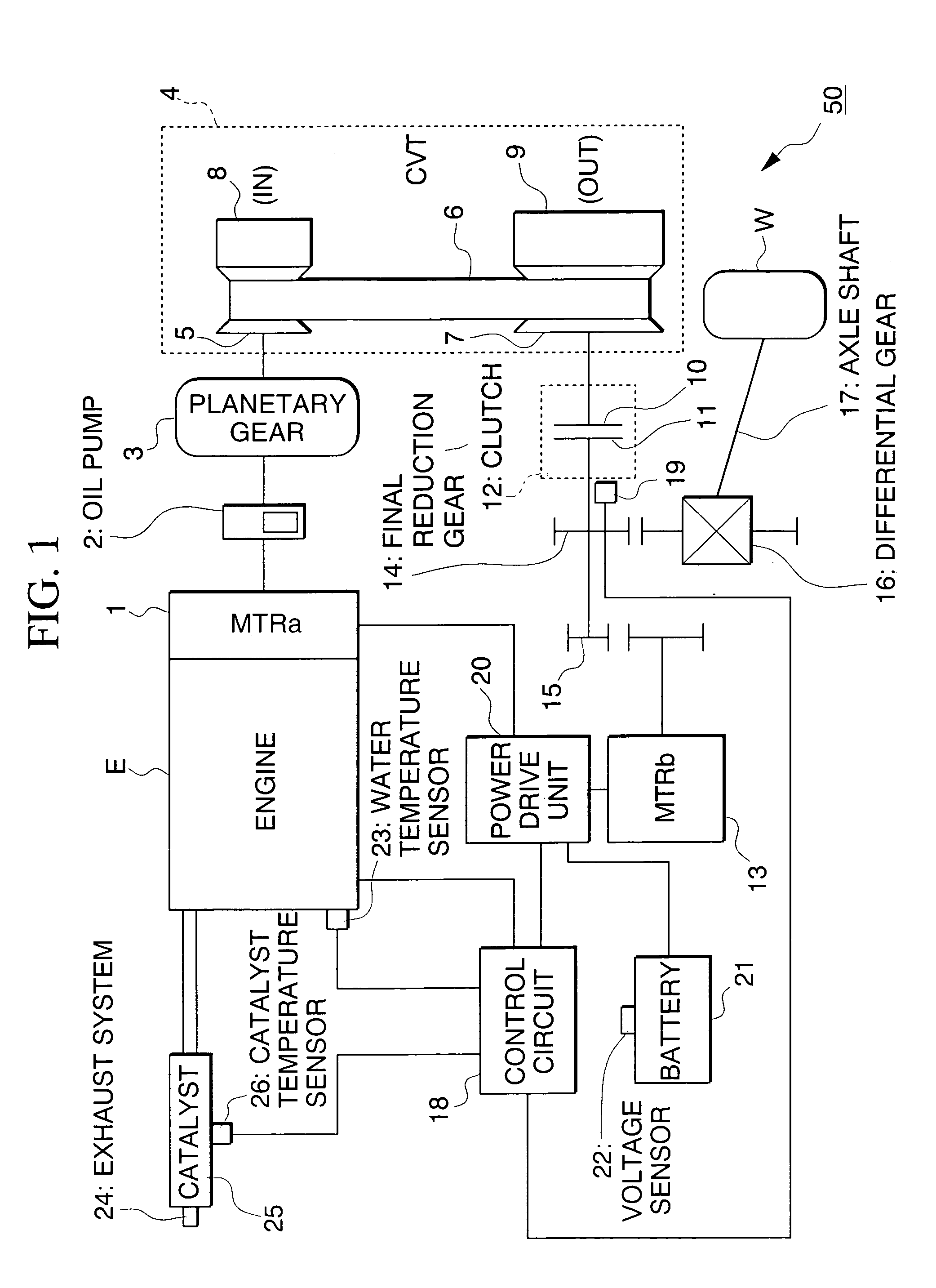
[0022]Hereinafter, the embodiment of the present invention is described with reference to the figures. FIG. 1 is a block diagram schematically showing the construction of the hybrid vehicle 50 of the first embodiment of the present invention. In this figure, the drive power from the engine E is input to a planetary gear 3 which switches between forward and reverse driving, via a submotor MTRa1 and an oil pump 2. The submotor MTRa1 receives the output from the engine E, generates electric energy, and outputs the generated electric energy to a power drive unit 20. The planetary gear 3 is mechanically connected to a selecting lever, not shown. When the driver switches the selecting lever, the rotational direction of the power from the engine E, which is input to a drive side pulley 5 of a CVT (Continuously Variable Transmission) 4, is switched.

[0023]The rotation of the drive side pulley 5 is transmitted via metal belt 6 to a driven side pulley 7. Here, the revolution ratio between the ...


PUM


Abstract

The catalyst warming control apparatus of the present invention is provided for a hybrid vehicle having an internal combustion engine, a generator for generating electric power from the output from the internal combustion engine, a power storage unit for storing electric power generated by the generator, and an electric motor driven by the electric power stored in the power storage unit, the hybrid vehicle being driven by at least one of the outputs from the internal combustion engine and the motor. The catalyst warming control apparatus includes a temperature detector for detecting the temperature of a catalyst or a value relating to the same; a first comparison circuit for comparing the detected result from the temperature detector with a preset reference value; and a control circuit for allowing the generator to generate electric power and to store the power in the power storage unit when the internal combustion engine is driven, and when the detected result by the temperature detector is equal to or below the reference value according to the output from the comparison circuit.

Description

BACKGROUND OF THE INVENTION[0001]1. Field of the Invention[0002]The present invention relates to a catalyst warming control apparatus for a hybrid vehicle, and in particular, a technique for cleaning exhaust gas discharged from a hybrid vehicle which has an electric motor and a internal combustion engine (hereinafter referred to simply as an “engine”).[0003]This application is based on Japanese Patent Application Nos. 11-240592 and 2000-193255, the contents of which are incorporated herein by reference.[0004]2. Description of the Related Art[0005]A catalyst for cleaning exhaust gas discharged from an engine, when it is cold, is not sufficiently activated, cannot satisfactorily perform the cleaning function, and there is a problem that the exhaust gas contaminated with pollutants may be discharged to the air.[0006]Conventional techniques detect the temperature of the catalyst, and activate the catalyst by reducing the engine speed and the load on the engine to restrict the discharge ...

Claims


Application Information

Patent Timeline
IPC IPC(8): F01N3/10B01D53/86F01N3/20B60K6/20B60K6/442B60K6/543B60L50/16B60W10/06B60W10/08B60W10/26B60W20/00F01N3/24F02D29/02F02D29/06F16H61/66
CPCB60K6/442B60K6/543B60W10/06B60W10/08B60W10/26B60W20/00B60K6/48Y10T477/23B60L2240/445B60W2510/0676B60W2510/068B60W2510/244B60W2710/0622F16H61/66Y02T10/52Y02T10/54Y02T10/6221Y02T10/6234Y02T10/6286Y02T10/40Y02T10/62B60K2006/268B60W20/40
Inventor ASAMI, KIYOSHIIBARAKI, SHIGERUKISHIDA, MAKOTO
Owner HONDA MOTOR CO LTD
Learn More