
Hybrid write mechanism for high speed and high density magnetic random access memory

a write mechanism and magnetic random access technology, applied in the field of magnetic random access memory, can solve the problems of increasing the density of the mram, consuming more power, and poor scaling of the writing scheme with increasing the density of the cell

Inactive Publication Date: 2006-02-28
SEAGATE TECH LLC
View PDF11 Cites 208 Cited by
  • Summary
  • Abstract
  • Description
  • Claims
  • Application Information

AI Technical Summary

Benefits of technology

"The patent describes a method and device for writing to a magnetic random access memory by using a magnetic field and current to change the magnetization of a free layer in a magnetoresistive element. The magnetic field can be produced by passing a current through conductors near the magnetoresistive element. The magnetic field can cause the magnetization of the free layer to precess around an equilibrium direction, and the current can be applied when the magnetization overshoots the equilibrium direction. The device can include a pinned layer and a nonmagnetic layer between the free layer and the pinned layer, or a first pinned layer, a first nonmagnetic layer, a second pinned layer, and a second nonmagnetic layer. The technical effects of this invention include improved data storage and retrieval in a magnetic random access memory."

Problems solved by technology

Unfortunately, this writing scheme exhibits poor scaling with increasing areal density of cells.
MRAM faces the same issue of thermal stability that is confronting hard disk drives.
This means that higher density MRAM will require larger magnetic fields in order to write bits, which will require larger currents through the word and bit lines that will consume more power.
However, this write process will have to overcome numerous reliability issues related to the large increases in temperature required to make this scheme work.
Thermally assisted writing will also face significant challenges in producing competitive writing speeds, as the process is fundamentally limited by the time (˜1 ns) it takes for thermal energy to transfer from the lattice (phonons) to the magnetic system.
However, even a write process based on spin momentum transfer will have to confront the increasingly burdensome requirement of having to reverse the magnetization of a FL having a larger anisotropy.

Method used


Image

  • Hybrid write mechanism for high speed and high density magnetic random access memory
  • Hybrid write mechanism for high speed and high density magnetic random access memory
  • Hybrid write mechanism for high speed and high density magnetic random access memory

Examples


Embodiment Construction

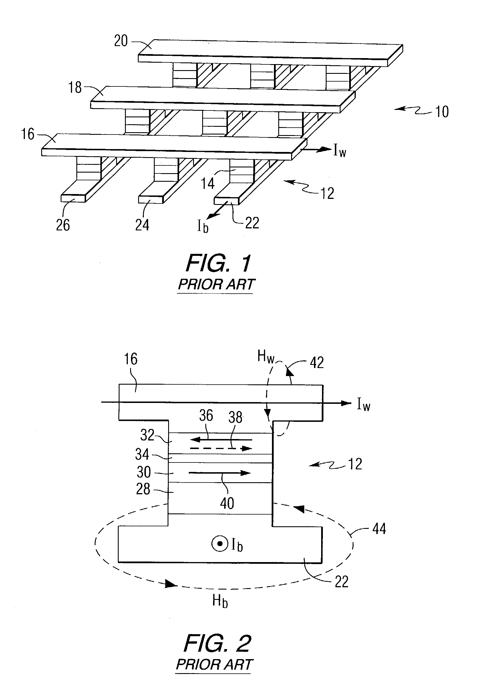
[0027]Referring to the drawings, FIG. 1 is a schematic representation of a conventional magnetic random access memory 10. MRAM 10 includes a 3×3 array of cells 12 that are a subset of the total number of cells comprising the MRAM device. Every cell contains one MR element 14. There are two roughly orthogonal sets of electrical wires, referred to as word lines 16, 18 and 20, and bit lines 22, 24 and 26, that overlap the MR elements. A bit is written only at the intersection of the word and bit lines that have current flowing through them.

[0028]FIG. 2 is a cross-sectional view of a MR element 14, which for this particular example is a magnetic tunnel junction. The MR element is connected between a word line 16 and a bit line 22, and includes an antiferromagnetic layer 28, a pinned layer 30 positioned on the antiferromagnetic layer, a free layer 32, and a nonmagnetic layer 34 between the pinned layer and the free layer. The arrows 36 and 38 in the free layer, and arrow 40 in the pinned...


PUM


Abstract

A method of writing to a magnetic random access memory comprising: producing a magnetic field along a magnetically hard axis of a free layer of a magnetoresistive element; and passing current through the magnetoresistive element to change a direction of magnetization of the free layer by spin momentum transfer. A magnetic random access memory that operates in accordance with the method is also included.

Description

FIELD OF THE INVENTION[0001]This invention relates to magnetic random access memory and, more particularly, to a method of writing to magnetic random access memory and magnetic random access memory that can be used to perform the method.BACKGROUND OF THE INVENTION[0002]Magnetic random access memory (MRAM) is a new technology that will likely provide superior performance over existing flash memory technology and may even supplant disk drives in certain low power applications requiring a compact non-volatile memory device. In MRAM, bits are represented by the magnetic configuration of a small volume of ferromagnetic material and its magnetic state is measured via a magnetoresistive (MR) effect during read-back. The MRAM typically includes a two-dimensional array of cells, with each cell containing one MR element that can store one bit.[0003]Most common MRAM designs employ MR elements that are based on either giant magnetoresistance (GMR) or tunneling magnetoresistance (TMR), where the...

Claims


Application Information

Patent Timeline
Patent Type & Authority Patents(United States)
IPC IPC(8): G11C11/15
CPCG11C11/15
Inventor COVINGTON, MARK WILLIAM
Owner SEAGATE TECH LLC
Learn More