
Slurry activation of Fischer-Tropsch catalyst with carbon monoxide co-feed

a carbon monoxide co-feed and slurry activation technology, which is applied in the direction of catalyst regeneration/reactivation, physical/chemical process catalysts, metal/metal-oxide/metal-hydroxide catalysts, etc., can solve the problems of inconvenient production, transportation technology challenges, and final cost of natural gas, so as to improve the efficiency and effect of in situ reduction, reduce the loss of slurry and production

Inactive Publication Date: 2006-02-21
CONOCOPHILLIPS CO
View PDF18 Cites 13 Cited by
  • Summary
  • Abstract
  • Description
  • Claims
  • Application Information

AI Technical Summary

Benefits of technology

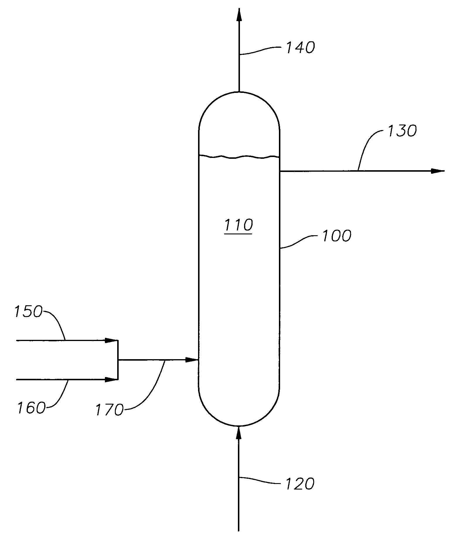
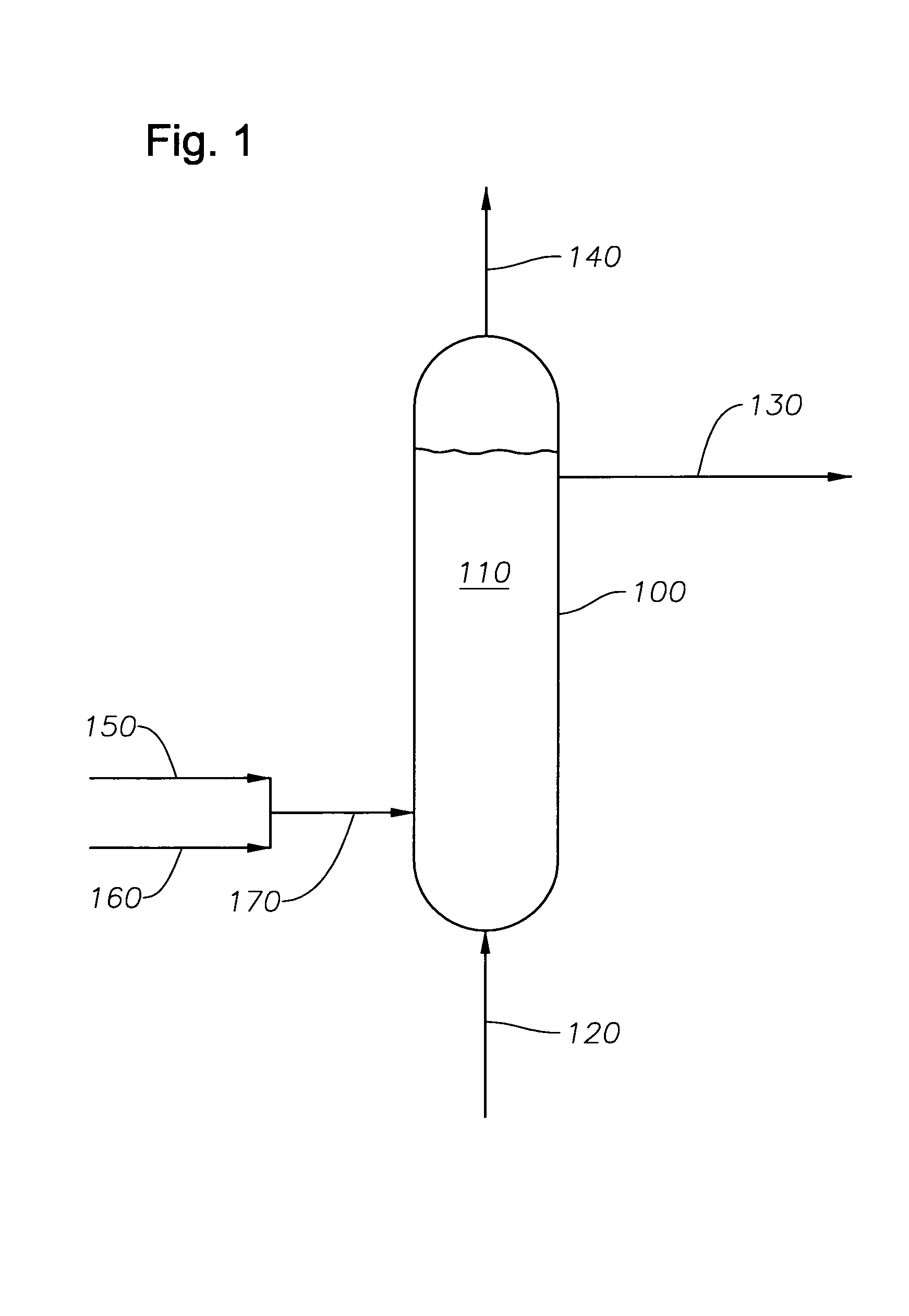
[0018]Accordingly, there are provided herein methods and apparatus for improving the efficiency and effectiveness of in situ reduction and / or regeneration of a Fischer-Tropsch catalyst slurry. The preferred embodiments of the present invention are characterized by a system that utilizes a co-feed of carbon monoxide and a reducing gas into a reduction vessel. Though not wishing to be bound by any theory, it is postulated that as the metal oxide reduces to the active Fischer-Tropsch metal, the carbon monoxide acts as a poison for hydrogenolysis and reduces the loss of slurry and the production of methane during the reduction.

Problems solved by technology

Wells that provide natural gas are often remote from locations with a demand for the consumption of the natural gas.
This transportation presents technological challenges due, in part, to the large volume occupied by a gas.
However, this contributes to the final cost of the natural gas and may not be economical.
Further, naturally occurring sources of crude oil used for liquid fuels such as gasoline, jet fuel, kerosene, and diesel fuel have been decreasing and supplies are not expected to meet demand in the coming years.
Iron has the advantage of being readily available and relatively inexpensive, but the disadvantage of a high water-gas shift activity.
Ruthenium has the advantage of high activity but is quite expensive.
The selectivity and activity of a typical Fischer-Tropsch catalyst will also, due to a number of factors, deteriorate over time.
At the preferred reduction temperatures, normally between 300 and 400° C., the reduction process may be susceptible to hydrogenolysis.
Whereas some processes take advantage of hydrogenolysis, it can be detrimental to a Fischer-Tropsch slurry.
This tends to lead to a loss of slurry liquid from the reaction vessel due to both methane formation and due to vaporization of the lighter components.
The above factors can cause a loss of reduction efficiency of the metal oxide leading to lower syngas conversion rates during the Fischer-Tropsch process.
Similarly, separating the catalyst from a slurry for regeneration is difficult and also adds complexity and cost to the Fischer-Tropsch process.
Carrying out regeneration or reduction at lower temperatures requires high amounts of noble metals in the catalyst, which adds to the cost of the catalyst.

Method used


Image

  • Slurry activation of Fischer-Tropsch catalyst with carbon monoxide co-feed
  • Slurry activation of Fischer-Tropsch catalyst with carbon monoxide co-feed
  • Slurry activation of Fischer-Tropsch catalyst with carbon monoxide co-feed

Examples


example 1

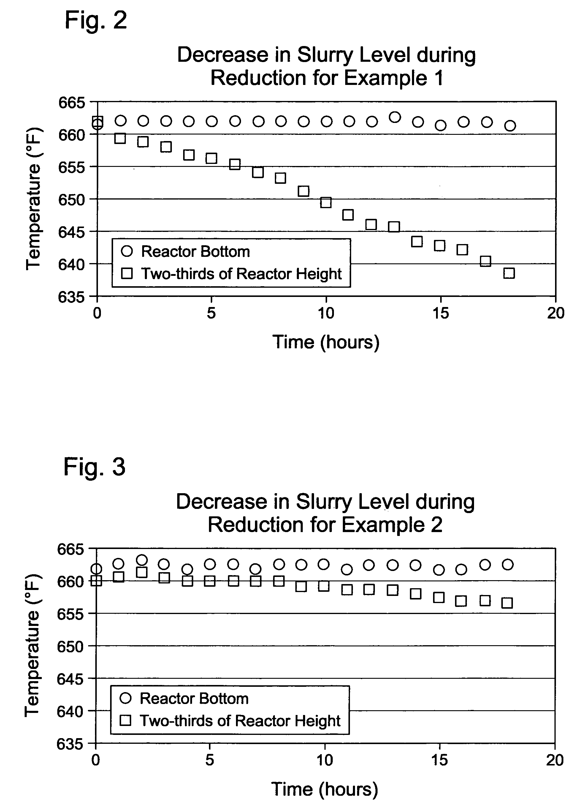
[0052]A 2.2-gram sample of a cobalt-based Fischer-Tropsch catalyst in the oxide form was loaded into the 600-ml stirred tank vessel with about 180 grams of a hydrocarbon oil to form a catalyst slurry in the vessel. The hydrocarbon oil was a neutralized base oil (typically used for lubricants manufacture) consisting of branched and straight chain paraffins with an average of 35 carbon atoms per molecule and an average molecular weight of 492 grams / mol. The base oil used in Example 1 was a base oil under the Registered Trademark of PURE PERFORMANCE® 600N from ConocoPhillips Company (Houston, Tex.). The cobalt-based Fischer-Tropsch catalyst comprised particles with an average particle size of about 70 microns. The catalyst was prepared by an impregnation technique followed by calcination to yield a catalyst composition of about 25 wt % cobalt and small amounts (<1 wt %) of promoters. Hydrogen was used as the reducing gas at a flow rate of 300 standard cubic centimeters per minute (sccm...

example 2

[0056]A 2.2-gram sample of the same cobalt-based Fischer-Tropsch catalyst in the oxide form as used in Example 1 was loaded into the 600-ml stirred tank vessel with 180 grams of hydrocarbon oil (same oil as in Example 1) to form the catalyst slurry. The reducing gas used in this Example 2 was a hydrogen gas containing 500 ppm by volume of carbon monoxide. Similar to Example 1, the reducing gas was used at a flow rate of 300 standard cubic centimeters per minute (sccm), and the pressure in the vessel was maintained at 60 psig.

[0057]The catalyst slurry was heated to the desired reduction temperature of 662° F. (350° C.) using the same heating rate as in Example 1: heating from ambient temperature to 240° F. at 2° F. / min, holding at 240° F. for one hour, and heating from 240° F. to 662° F. at 2° F. / min. The catalyst slurry was maintained at 662° F. for 18 hours.

[0058]The measured gas flow rate at the vessel exit was 300 sccm. The composition of the exit gas was 1.6 mole percent methane...


PUM

PropertyMeasurementUnit
temperatureaaaaaaaaaa

Abstract

Methods and apparatus for improving the efficiency and effectiveness of in situ reduction of a Fischer-Tropsch catalyst slurry. The preferred embodiments of the present invention are characterized by a system that utilizes a co-feed of carbon monoxide along with the reducing gas into a reduction vessel maintained at an elevated temperature. As the metal oxide reduces to the active Fischer-Tropsch metal, the carbon monoxide acts as a poison to hydrogenolysis and reduces the loss of liquid from the slurry and the production of methane. The carbon monoxide is generally in parts-per-million quantities and will achieve the desired results in quantities less than 5,000 ppm, preferably less than 2,000 ppm.

Description

CROSS-REFERENCE TO RELATED APPLICATIONS[0001]The present application claims the benefit of 35 U.S.C. 111(b) Provisional Application Ser. No. 60 / 412,598 filed Sep. 20, 2002, and entitled “Slurry Activation and Regeneration of Fischer-Tropsch Catalyst With Carbon Monoxide Co-Feed,” which is hereby incorporated by reference herein for all purposes.STATEMENT REGARDING FEDERALLY SPONSORED RESEARCH OR DEVELOPMENT[0002]Not applicable.TECHNICAL FIELD OF THE INVENTION[0003]The present invention relates generally to methods and apparatus for decreasing hydrogenolysis during the reduction of a catalyst slurry by feeding a stream of carbon monoxide to the slurry. More specifically, the present invention relates to methods and apparatus for co-feeding a stream of carbon monoxide into a Fischer-Tropsch catalyst slurry during high temperature reduction and / or regeneration in order to reduce hydrogenolysis in the slurry.BACKGROUND OF THE INVENTION[0004]Natural gas, found in deposits in the earth, i...

Claims


Application Information

Patent Timeline
Patent Type & Authority Patents(United States)
IPC IPC(8): C07C27/00B01J23/75B01J23/94B01J37/18B01J38/10B01J38/58C10G2/00
CPCB01J23/75B01J23/94C10G2/32B01J38/10B01J38/58B01J37/18
Inventor RAJE, AJOY P.
Owner CONOCOPHILLIPS CO
Learn More