Sterilization container filter system

Inactive Publication Date: 2006-02-21
CAREFUSION 2200 INC
View PDF49 Cites 21 Cited by
  • Summary
  • Abstract
  • Description
  • Claims
  • Application Information

AI Technical Summary

Benefits of technology

[0007]The invention provides a filter system for sterilization containers comprising a locking mechanism that is comfortable and easy to use and that requires a simple sliding movement of the users hand to lock and unlock the filter. It has further been discovered that a filter system can be constructed to reduce or eliminate the need for precise positioning of filter components in relation to one another by the user to prevent the likelihood of physical puncture of the filter while at the same time permitting the unobstructed transport of air across the filter layer. The filter system of the invention is also relatively easy to manufacture. The filter system of the invention also does not require the use of gaskets circumscribing the perimeter of the system. The invention is particularly useful in a variety of medical applications wherein sterilization of medical devices and instruments is needed for a surgical treatment or procedure.
[0017]wherein linear sliding movement of said locking plate increases the vertical compressive force between the filter system components.

Problems solved by technology

One drawback of this system, however, is that it requires a turning or pivoting movement by the user's hand, and does not provide a penetration resistant structure to protect the filter from piercing.
This system, however, requires precise positioning of the retainer discs in relation to one another and the vent openings, and does not contain a single, centrally located locking mechanism.

Method used


Image

  • Sterilization container filter system
  • Sterilization container filter system
  • Sterilization container filter system

Examples


Embodiment Construction

[0039]As used herein, the term “plate” is meant to refer to a component having a substantially planar construction. The term is not intended to imply a limitation as to a particular perimeter configuration, such as a circular, disc-like shape.

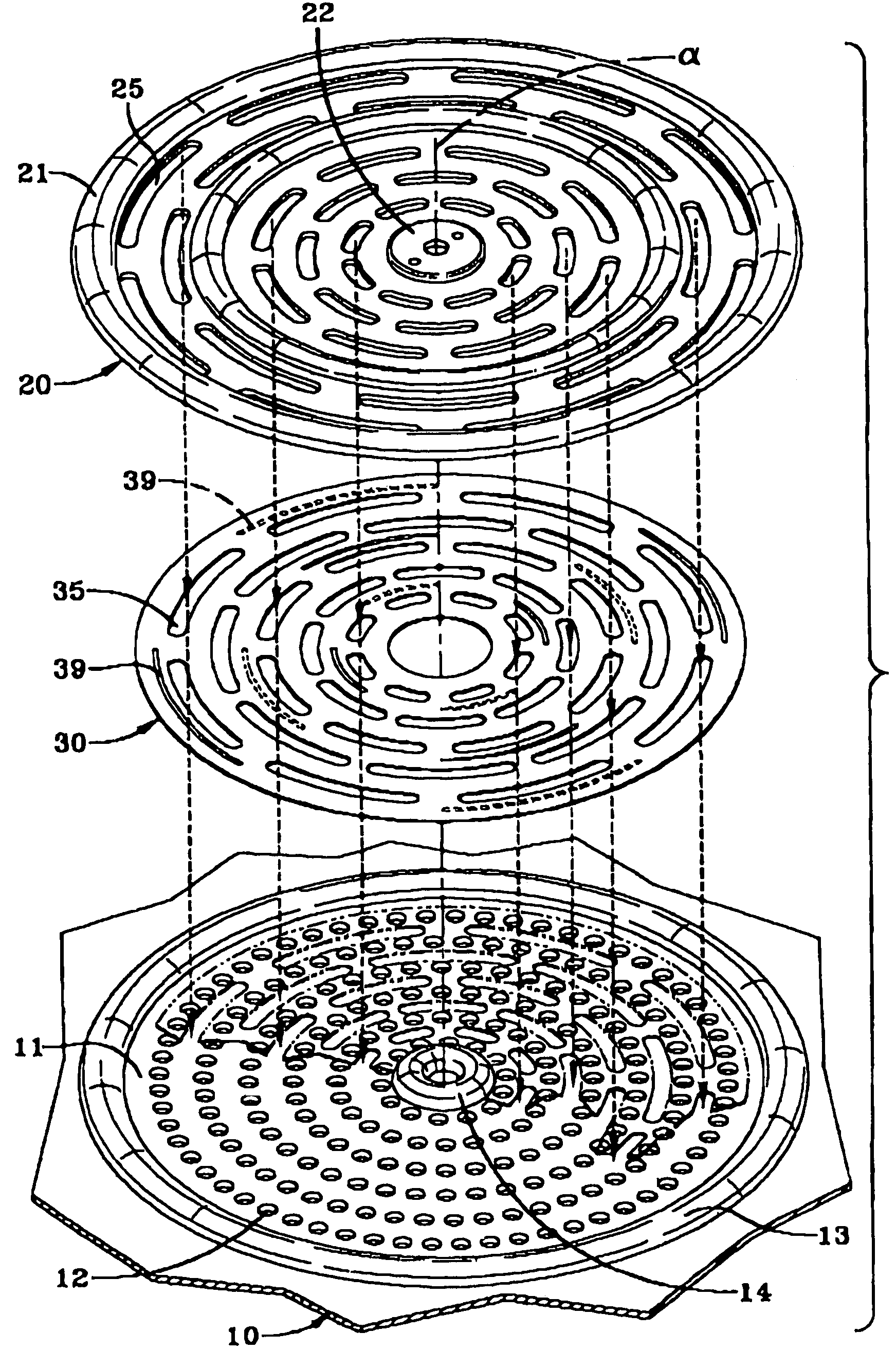
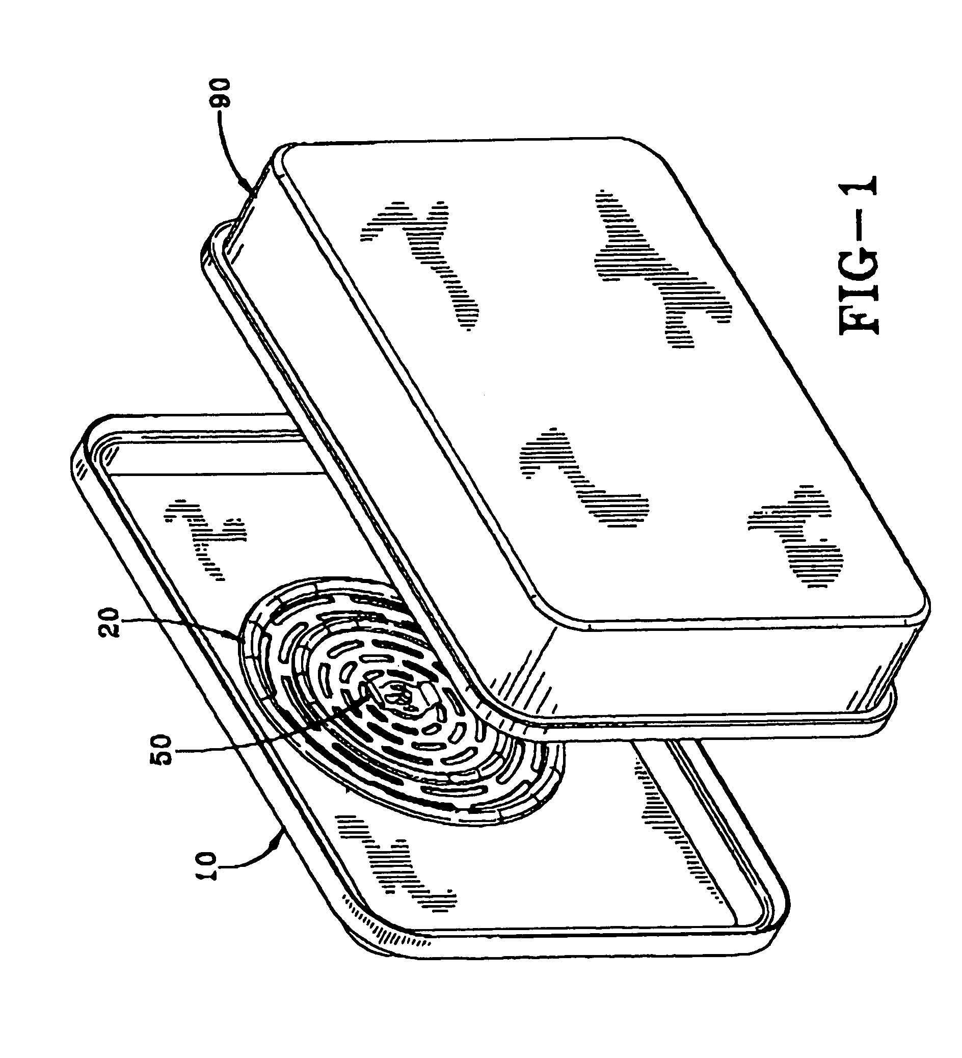
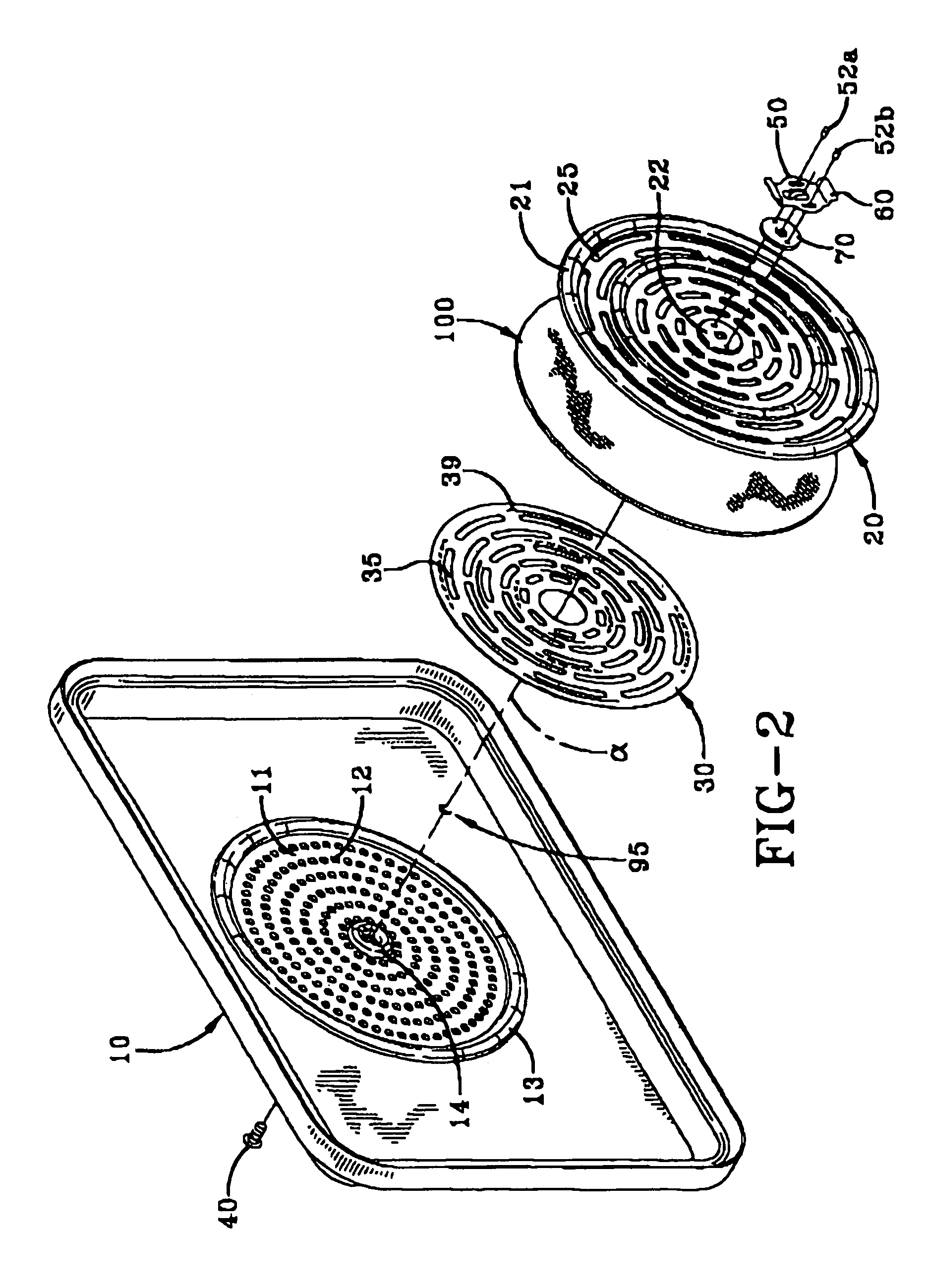
[0040]In general, the filter system of the invention is designed for use as a component in a sterilization container. Suitable sterilization containers for use with the filter system of the invention can include a basic construction of a lid and base portion, wherein at least one of either the lid, the base, or both, contains a vented portion. For purposes of illustration, the invention is depicted in the drawings as having the filter system located on the lid, the lid containing the vented portion of the container. In a further embodiment, a sterilization container can be constructed to have more than one vented opening and corresponding filter system therewith. The filter system of the invention performs the overall function of securing a gas...


PUM

PropertyMeasurementUnit
Permeabilityaaaaaaaaaa
Perimeteraaaaaaaaaa

Abstract

The invention described herein relates to a filter system for sterilization containers which secures a gas permeable filter onto a vented portion of the container. The filter system of the invention includes a locking mechanism that is comfortable and easy to use, and that requires a simple sliding movement of the users hand to lock and unlock the filter system components in place. The invention further includes a filter system structured such that the openings of the filter system plates permit transport of air across the filter while at the same time the openings are arranged to reduce or prevent undesirable physical perforation of the filter. By virtue of its structure, the need for particular rotational positioning of filter components in relation to one another is significantly reduced. The filter system of the invention also reduces or eliminates the need for perimeter gaskets. The invention is useful in a variety of medical applications wherein sterilization of medical devices and instruments is associated with a surgical treatment or procedure.

Description

RELATED APPLICATION DATA[0001]This application is a divisional of U.S. patent application Ser. No. 10 / 199,447 filed Jul. 18, 2002, now pending.FIELD OF THE INVENTION[0002]The invention relates to the field of sterilization containers used for the sterilization of medical devices. In particular, the invention pertains to a filter retention system used with sterilization containers.BACKGROUND OF THE INVENTION[0003]Prior to medical and surgical procedures or treatments, sterilization of medical devices and instruments prior to their use is necessary to reduce the risk of infection from microbes on such equipment. Various sterilization techniques are utilized in the medical field, such as irradiation of equipment, treatment using antimicrobial solutions, and temperature sterilization techniques. One of the most commonly employed techniques is sterilization using an autoclave, which involves placement of the equipment to be sterilized within a chamber which is subsequently heated to a te...

Claims


Application Information

Patent Timeline
IPC IPC(8): A61L2/20A61L2/02A61L2/26
CPCA61L2/022A61L2/07A61L2/26A61L2202/24A61L2202/122Y10T70/50
Inventor BAUER, WITOLD
Owner CAREFUSION 2200 INC
Why Eureka
Try Eureka