Head for injecting a fluid under pressure to break up ground from a borehole

a technology of jet grouting and nozzle, which is applied in the direction of soil preservation, cutting machines, fluid removal, etc., can solve the problems of requiring considerable kinetic energy, and reducing the drilling efficiency of the drilling machine, so as to reduce the disturbance of the flow, shorten the drilling time, and improve the quality of the jet produced by the nozzle

Inactive Publication Date: 2006-02-21
CIE DU SOL
View PDF5 Cites 5 Cited by
  • Summary
  • Abstract
  • Description
  • Claims
  • Application Information

AI Technical Summary

Benefits of technology

[0012]An object of the present invention is to provide an injection head, in particular for implementing jet grouting, which serves to improve more significantly the quality of the jet supplied by the nozzle(s) of the injection head mounted at the bottom end of the drill string, while also making it possible with the same injection head to feed the mechanical drilling tool.
[0016]It will be understood that the quality and the direction of the jet produced by the nozzle are significantly improved because of the progressive and regular reduction in the right section of the duct-forming means, for example a tube, over at least half of its length from its end for connection to the fluid feed pipe, usually liquid under pressure, to its end for connection to the inlet orifice of the injection nozzle. This characteristic combined with the fact that the mean line of the duct-forming means presents a radius of curvature that varies regularly, makes it possible to minimize the disturbance to the flow of liquid in said tube and thus to obtain a jet with maximum energy and of erosive power that is maintained at a maximum distance away from the nozzle in the ground.
[0017]In addition, the monitor makes it possible selectively to feed the nozzle(s) or to feed both the nozzle(s) and the mechanical drilling tool. It is thus possible to perform two types of operation without changing the tool that is fixed to the end of the drill string This option makes it possible to shorten the time required for drilling very significantly.

Problems solved by technology

However, even with such nozzles, it is found that the jet quickly loses effectiveness in terms of its ability to erode the ground, such that considerable amounts of kinetic energy are required, so that when the rods are moved in translation, and possibly also in rotation, the ground is eroded at a considerable distance from the nozzle, for example at a distance of several decimeters (dm).
The technique described in that above-mentioned United States patent is therefore not completely satisfactory, in particular because of said differences in section.
Such a disposition leads to significant disturbances in the flow of liquid at the inlet to the tube 26, and thus in the nozzle.
In addition, the monitor described in that patent does not enable the mechanical tool that might be mounted on the monitor to be fed with liquid under pressure.
Unfortunately, it is necessary to feed the mechanical tool with drilling liquid in order to lubricate it, and above all in order to raise the cuttings that result from the drilling.

Method used


Image

  • Head for injecting a fluid under pressure to break up ground from a borehole
  • Head for injecting a fluid under pressure to break up ground from a borehole
  • Head for injecting a fluid under pressure to break up ground from a borehole

Examples


Embodiment Construction

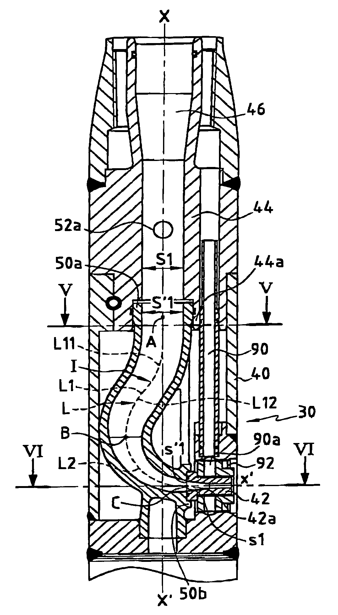
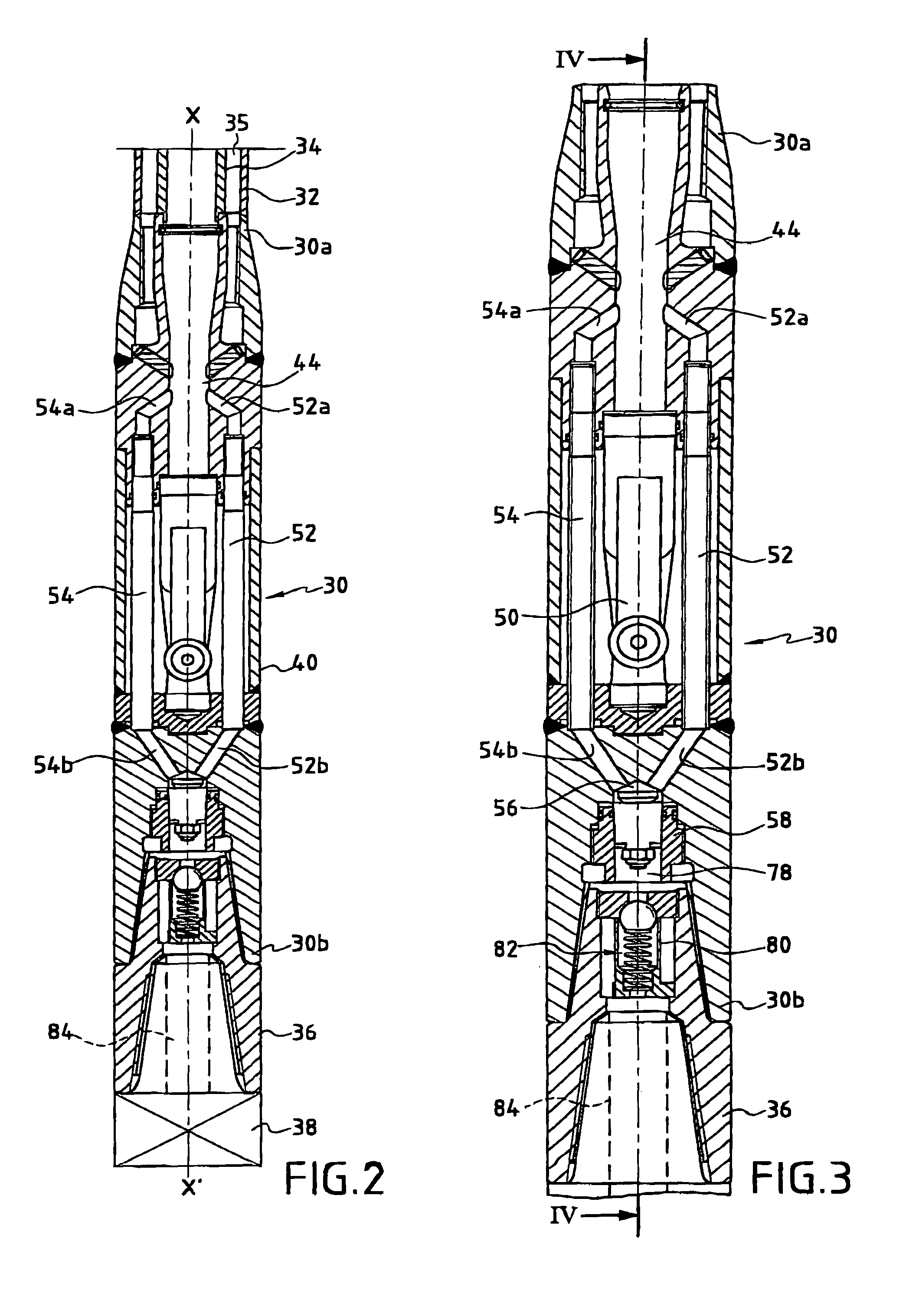
[0028]The drilling tool is described initially with reference to FIG. 2. The tool is essentially constituted by an injection head or monitor 30 which, as explained in greater detail below, serves to deliver a jet of liquid under pressure, or more generally a jet of fluid under pressure, which is delivered via a nozzle to break up the wall of a borehole. The liquid under pressure is typically a grout or an analogous filled liquid. The top end 30a of the monitor 30 is connected to drill strings such as 32 in order to lower the tool and set it in rotation. The string of drill rods 32 is preferably fitted with an inner coaxial pipe 34 serving to convey the liquid under pressure for feeding the injection nozzle and the mechanical drilling tool. At the bottom end 30b of the monitor 30 there is mounted an intermediate part 36, itself serving for mounting the mechanical drilling tool 38 or bottom tool.

[0029]The injection head 30 comprises a body having an outer wall 40 of generally cylindri...


PUM


Abstract

The present invention provides a head for injecting a fluid under pressure for breaking up the ground from a borehole and mounted at the end of a string of rods. The body of the drilling head has a bottom wall for mounting a mechanical drilling tool having a feed pipe, at least one injection nozzle, and duct-forming means for connecting the feed pipe with liquid at the inlet of said nozzle, the duct-forming means presenting a mean line having a radius of curvature that varies continuously, the right section of said duct-forming means decreasing regularly over at least half its length from its first end towards its second end. The injection head further comprises at least one pipe for feeding said mechanical tool, said pipe being connected at a first end to said duct-forming means and at a second end to a chamber disposed at the bottom end of said injection head and fitted with a controllable shutter member interposed between said chamber and the pipe for feeding said mechanical tool.

Description

[0001]The present invention relates to a head for injecting a fluid under pressure, usually a liquid, which head may be fitted to a boring tool for boring an excavation in the soil, and the invention relates in particular to an injection head for implementing the technique known as “jet grouting”.BACKGROUND OF THE INVENTION[0002]The jet grouting technique consists in breaking up the ground by means of a jet of fluid having very high kinetic energy that is delivered in a borehole, the jet of fluid eroding the soil in which it is desired to make an excavation. To form the jet, a nozzle is used which is fixed to the end of drilling rods, these rods serving both to convey the fluid under high pressure to the nozzle(s) and to move the nozzle progressively into the ground. More precisely, the nozzle(s) is / are mounted on a member usually referred to as a “monitor” or an “injection head” which is fixed to the bottom end of the drill string, said monitor itself possibly being fitted at its o...

Claims


Application Information

Patent Timeline
Patent Type & Authority Patents(United States)
IPC IPC(8): E21B7/26E02D3/12E02D5/46E02D27/26E21B7/18
CPCE02D5/46E21B7/18E02D27/26
Inventor GESSAY, JEAN-CLAUDEMOREY, JACQUESMATHIEU, FABRICE
Owner CIE DU SOL
Why Eureka
Try Eureka