
Electric keyboard assembly and method of manufacturing weight members provided in keyboard assembly

a technology of keyboard assembly and weight member, which is applied in the direction of wind musical instruments, electrophonic musical instruments, stringed musical instruments, etc., can solve the problems of reducing the above-mentioned space or room, limiting the size of the weight member, and limited degree of freedom in mass distribution, so as to reduce the height of the keyboard, facilitate key scaling to key-touch responses, and maintain the degree of freedom in keyboard design

Inactive Publication Date: 2006-02-07
YAMAHA CORP
View PDF12 Cites 18 Cited by
  • Summary
  • Abstract
  • Description
  • Claims
  • Application Information

AI Technical Summary

Benefits of technology

[0010]It is a first object of the present invention to provide an electric keyboard assembly which can have a reduced height of a keyboard and at the same time maintain the degree of freedom in designing the keyboard to facilitate key scaling to key-touch responses.
[0011]It is a second object of the present invention to provide an electric keyboard assembly which has a uniform key-touch response between each adjacent white and black keys, and allows mass members to have a uniform resin portion, thereby making it possible to simplify the construction of each mass member, facilitate the manufacture and assembly work thereof, and reduce manufacturing costs of the electronic keyboard assembly.
[0012]It is a third object of the present invention to provide an electric keyboard assembly having a construction which makes it possible to easily accomplish key scaling to key-touch responses and make mass members as uniform in construction as possible, thereby making it possible to simplify the construction of each mass member, facilitate the manufacture and assembly work thereof, and reduce manufacturing costs of the electronic keyboard assembly.

Problems solved by technology

This causes an increased vertical travel distance of the weight portion of each mass member when the mass member is pivoted, which further reduces the above-mentioned space or room.
Further, when the weight member is mounted in the vicinity of the follower which is normally formed in one arm of the mass member, the size of the weight member has to be limited to prevent interference between the weight member and keys adjacent thereto.
As a result, the degree of freedom in mass distribution is limited, which hinders proper key scaling to key-touch response.
As a result, the number of types of mass members used is increased, which increases the variety of configuration of the mass members, resulting in increased difficulty in mounting of mass members on the body of the keyboard assembly and increased manufacturing costs.
Moreover, it is not easy to carry out mass distribution over each mass member.
Therefore, in the conventional electric keyboard assembly, uniformity or consistency in construction of the mass members cannot be ensured in carrying out proper key scaling to key-touch response, especially between the low-pitch keys and the high-pitch keys or between the white keys and the black keys.
In short, it is difficult to carry out key scaling to key-touch response without complicating the configurations of mass members.

Method used


Image

  • Electric keyboard assembly and method of manufacturing weight members provided in keyboard assembly
  • Electric keyboard assembly and method of manufacturing weight members provided in keyboard assembly
  • Electric keyboard assembly and method of manufacturing weight members provided in keyboard assembly

Examples


Embodiment Construction

[0061]The present invention will now be described in detail with reference to drawings showing a preferred embodiment thereof.

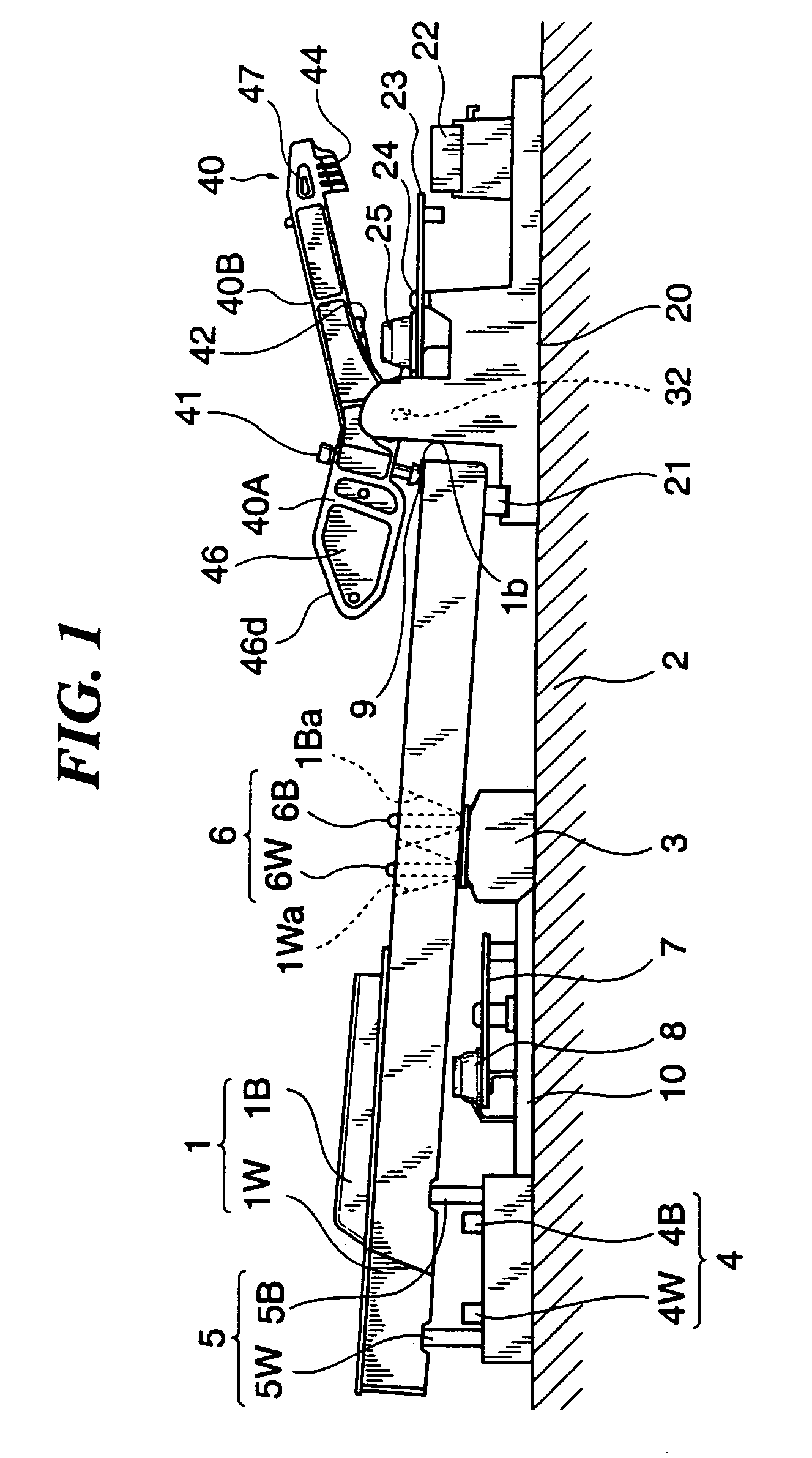
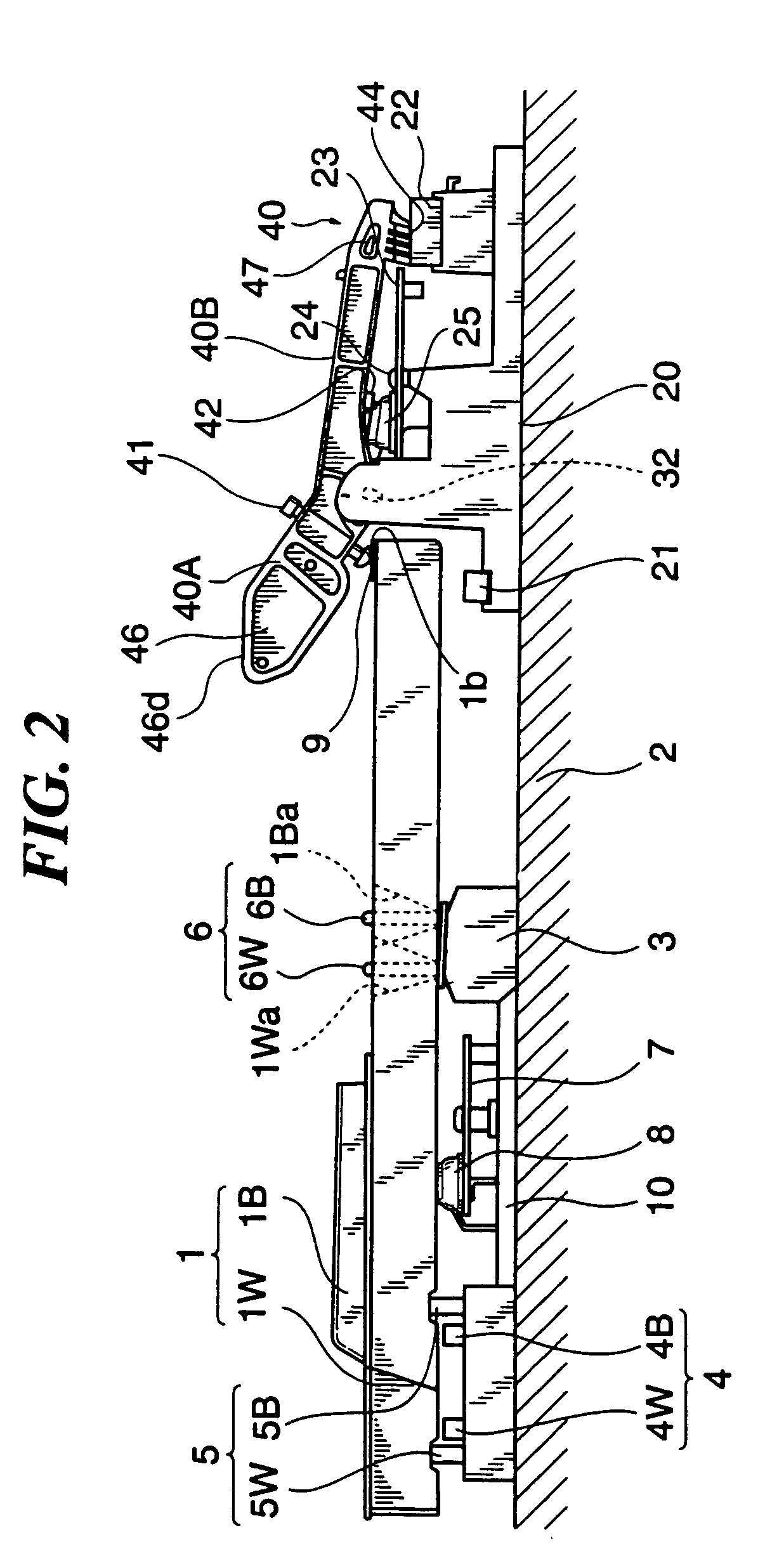
[0062]FIGS. 1 and 2 are cross-sectional views of essential parts of an electronic keyboard assembly as an electric keyboard assembly according to an embodiment of the present invention, in which FIG. 1 shows a non-key-depression state (i.e. a state where each of a key 1 and a mass member 40, referred to hereinafter, is in its pivotal movement-starting position), and FIG. 2 shows a full-key-depression state (i.e. a state where each of the key 1 and the mass member 40 is in its pivotal movement-completing position). An upper casing and a lid are omitted in the figures. In the following, a player side (left side, as viewed in FIG. 1) of the keyboard assembly will be referred to as “front” or “forward”, while a remote side (right side, as viewed in FIG. 1) of the same from the player will be referred to as “rear” or “rearward”.

[0063]The keyboard assembly is compr...


PUM


Abstract

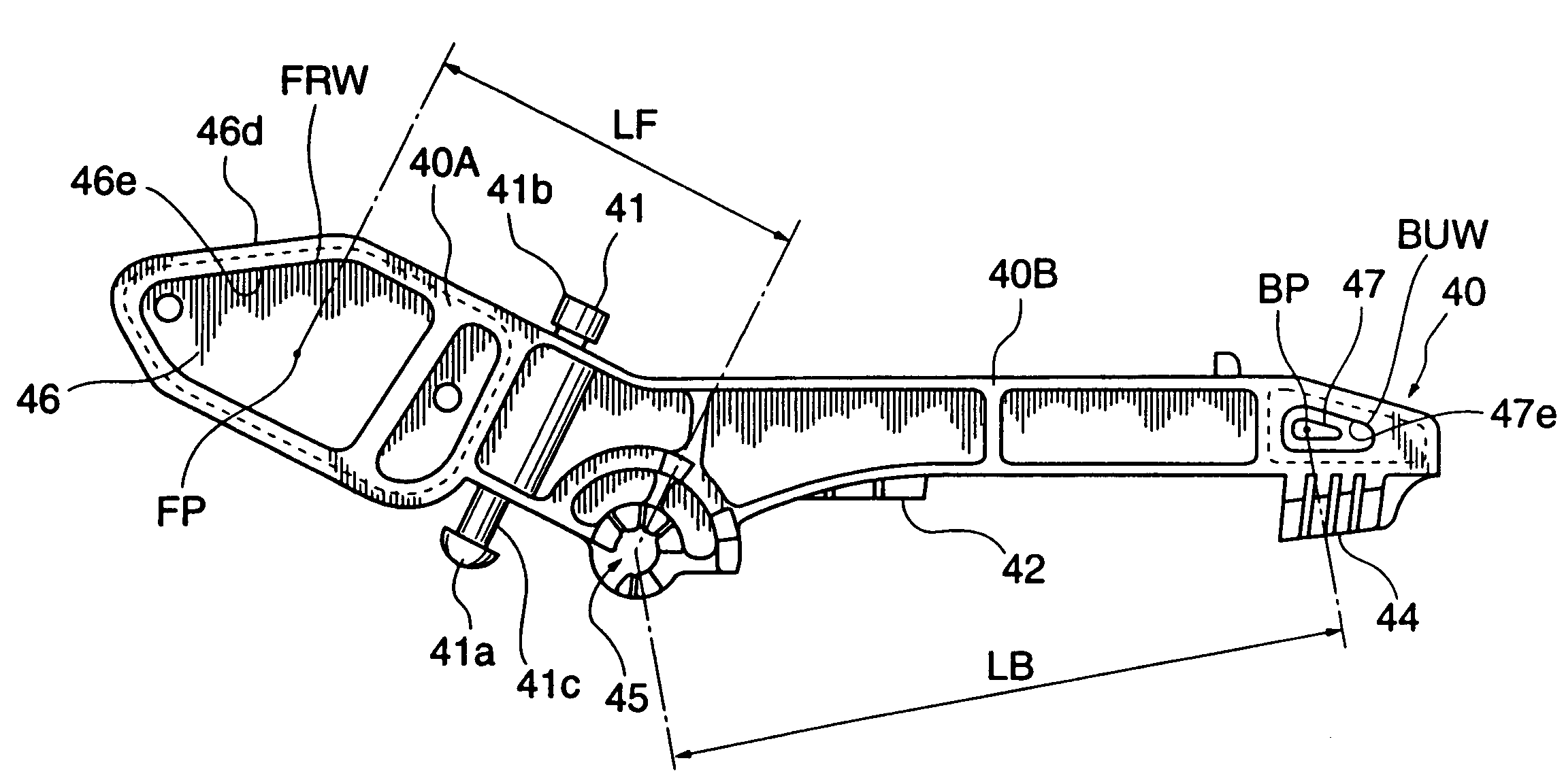
There is provided an electric keyboard assembly having a construction which is capable of reducing a height of a keyboard and at the same time facilitating key scaling to key-touch response while maintaining the degree of freedom in designing the keyboard. A key is pivotally moved by a key depressing operation. A seesaw-type mass member having a front extension and a rear extension each extending from a pivot-receiving portion thereof, and a tone-generating position adjustment screw fitted in the front extension is pivotally moved about the pivot-receiving portion by a driving force generated by depression of the key and received via the tone-generating position adjustment screw. The front extension of the mass member pops up to a level higher than the key when the key is depressed. A front weight and a back weight are arranged separately in the front extension and in the rear extension, respectively. A distance between the pivot-receiving portion and the front weight arranged in the front extension is set to be shorter than the distance between the pivot-receiving portion and the back weight member arranged in the rear extension.

Description

BACKGROUND OF THE INVENTION[0001]1. Field of the Invention[0002]This invention relates to an electric keyboard assembly which is provided with mass members each pivotally moved by depression of a corresponding key, and a method of manufacturing weight members provided in such a keyboard assembly.[0003]2. Prior Art[0004]Conventionally, an electronic keyboard assembly is known, in which mass members (hammer members) each having an appropriate mass are driven for pivotal movement by depression of corresponding keys, to thereby provide a simulated key-touch response of an acoustic piano.[0005]For instance, in a keyboard assembly of this kind, seesaw-type mass members each have an arm formed with a follower, and a driving force generated by depression of a corresponding key is transmitted from the key to the follower directly or indirectly via an intermediate member, to cause pivotal movement of the mass member. Further, a proper moment of inertia is applied to each mass member e.g. by t...

Claims


Application Information

Patent Timeline
IPC IPC(8): G10H1/34G10B3/12
CPCG10H1/346
Inventor NISHIDA, KENICHIMORI, NAOHISAISHIHARA, HIDEKI
Owner YAMAHA CORP
Learn More