Steel beam coupling device
a technology of coupling device and steel beam, which is applied in the direction of coupling, rod connection, manufacturing tools, etc., can solve the problems of notch or stress concentration around the hole, increase the construction cost of bolt installation, and undesirable performance, and achieves easy installation and good structural performance.
- Summary
- Abstract
- Description
- Claims
- Application Information
AI Technical Summary
Benefits of technology
Problems solved by technology
Method used
Image

Examples
embodiment 1
[0073]FIG. 13 illustrates Preferred Embodiment 1 of the present invention. In this figure, coupling device of the present invention are used to connect two H-shaped members (10). The two coupling cases (20) to connect the top flange are the type of coupling device exhibited in FIG. 6, and the web is connected using the coupling device shown in FIG. 7, and the bottom flange is connected using the separate-type coupling device exhibited in FIG. 10. FIG. 13 shows that different types of coupling devices can be used for one joint depending on conditions, though it is not usual in construction field.
[0074]Other types of coupling cases (20) illustrated in FIG. 11 or FIG. 12 can be applied in FIG. 13.
embodiment 2
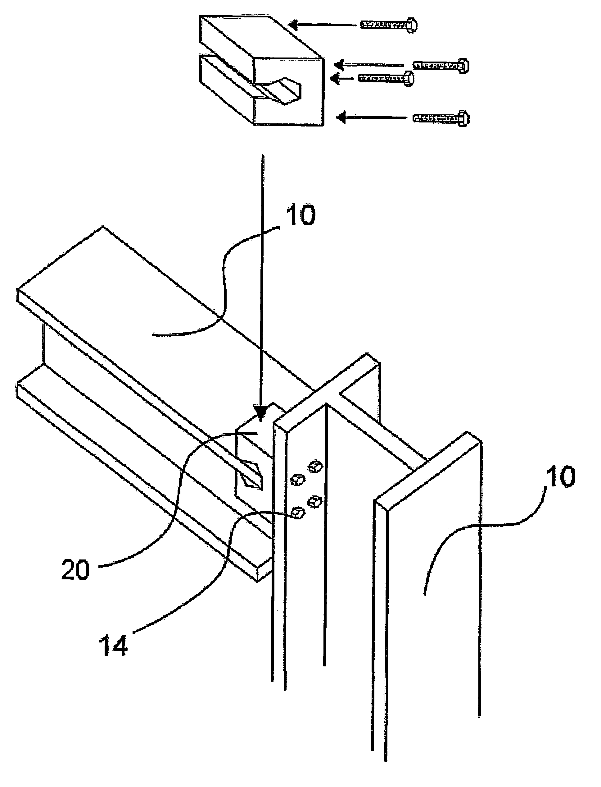
[0075]FIG. 14 illustrates Preferred Embodiment 2 of the present invention. The coupling device of the present invention connects two H-shaped members (10) that meet at right angle.
[0076]In this figure, the coupling case (20) has three connecting slots. Two connecting slots are used for one member (vertical member in the figure) to resist two external forces acting in two directions. One connecting slot is used for the other member (horizontal member in the figure) to resist external force in one direction.
[0077]FIG. 15 illustrates Preferred Embodiment 3 of the present invention. Compared with Preferred Embodiment 2, one member (horizontal member in the figure) is rotated by 90° about its axis. Preferred Embodiment 3 employs the coupling case (20) exhibited in FIG. 12 to resist external forces in two directions.
embodiment 4
[0078]FIG. 16 illustrates Preferred Embodiment 4 of the present invention. In this preferred embodiment, coupling case (20) of the present invention has a connecting slot on one side only. The other flat side is connected to a member using bolts.
[0079]FIG. 17 illustrates Preferred Embodiment 5 of the present invention. The coupling device (20) of the present invention connects one member to another of larger size which is welded to a column member using the method of Preferred Embodiment 1.
[0080]As shown in the figure, the width and the thickness of two members are different. Two members of different sizes can be connected by adjusting the length and / or the height of the connecting slots. The coupling device of the present invention can be used to improve the seismic performance of structural frame during severe earthquake by moving the plastic hinge away from the beam-to-column welds.
PUM
 Abstract
Description
Claims
Application Information
 - R&D
- Intellectual Property
- Life Sciences
- Materials
- Tech Scout
- Unparalleled Data Quality
- Higher Quality Content
- 60% Fewer Hallucinations
Browse by: Latest US Patents, China's latest patents, Technical Efficacy Thesaurus, Application Domain, Technology Topic, Popular Technical Reports.
© 2025 PatSnap. All rights reserved.Legal|Privacy policy|Modern Slavery Act Transparency Statement|Sitemap|About US| Contact US: help@patsnap.com