
Distributing fault indications and maintaining and using a data structure indicating faults to route traffic in a packet switching system

a packet switching system and fault indication technology, applied in data switching networks, instruments, frequency-division multiplexes, etc., can solve problems such as typical cost of approaches

Inactive Publication Date: 2006-01-24
CISCO TECH INC +1
View PDF46 Cites 91 Cited by
  • Summary
  • Abstract
  • Description
  • Claims
  • Application Information

AI Technical Summary

Benefits of technology

The patent describes a system for detecting and responding to errors in a network that connects multiple devices. When an error is detected, the system alerts all the devices connected to it. This helps to quickly identify and fix any problems in the network.

Problems solved by technology

Such approaches are typically costly.

Method used


Image

  • Distributing fault indications and maintaining and using a data structure indicating faults to route traffic in a packet switching system
  • Distributing fault indications and maintaining and using a data structure indicating faults to route traffic in a packet switching system
  • Distributing fault indications and maintaining and using a data structure indicating faults to route traffic in a packet switching system

Examples


Embodiment Construction

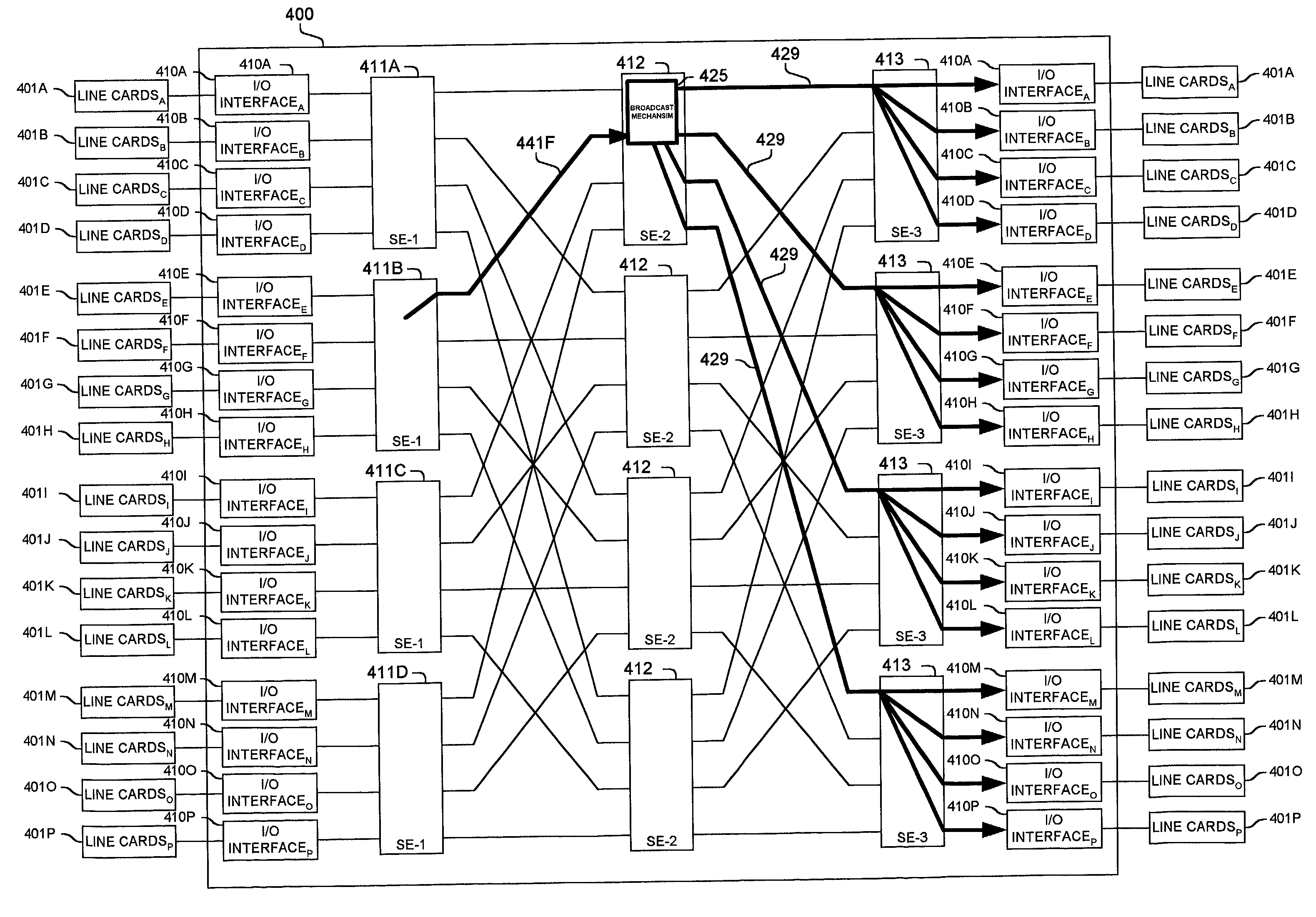
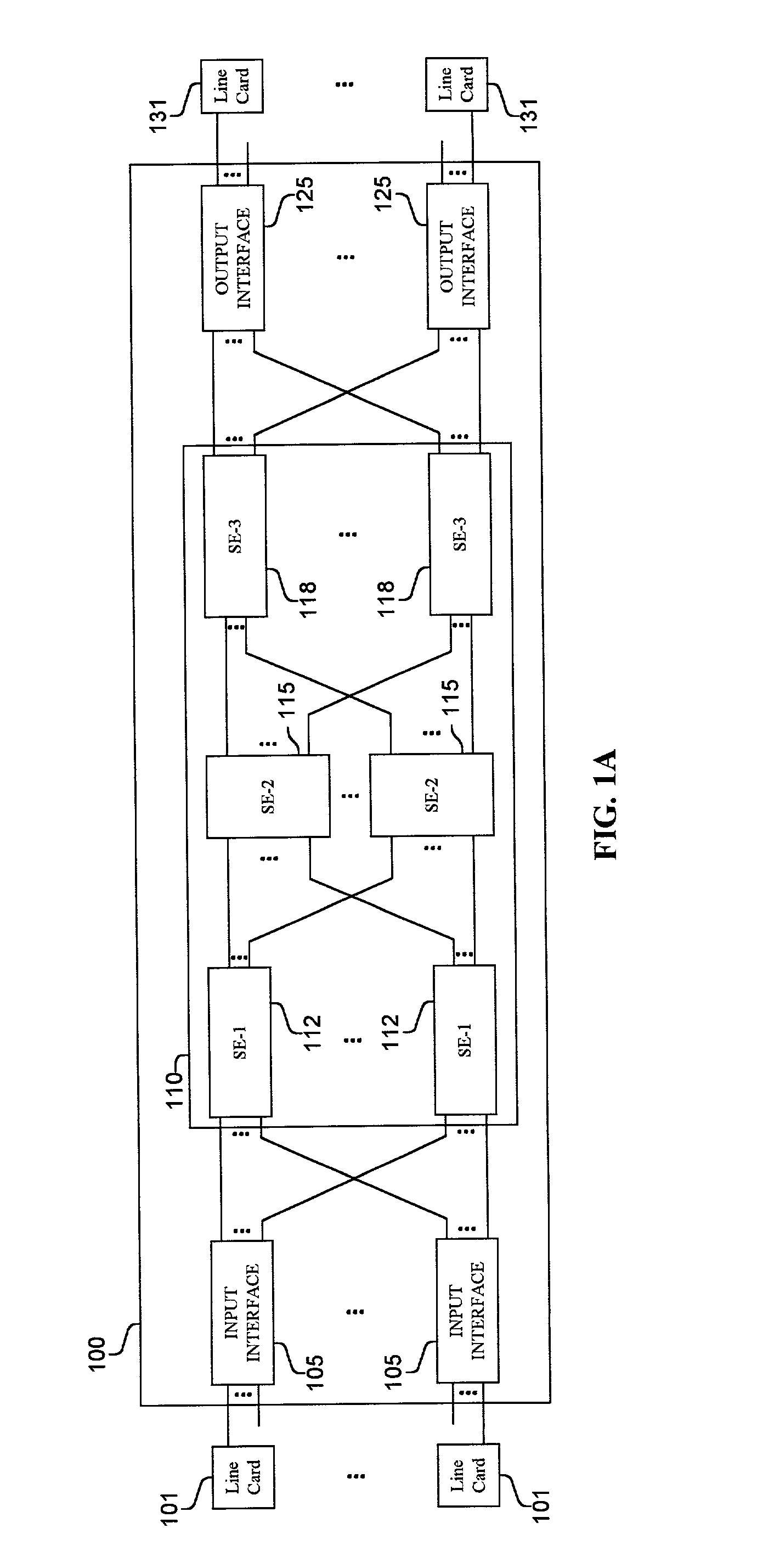
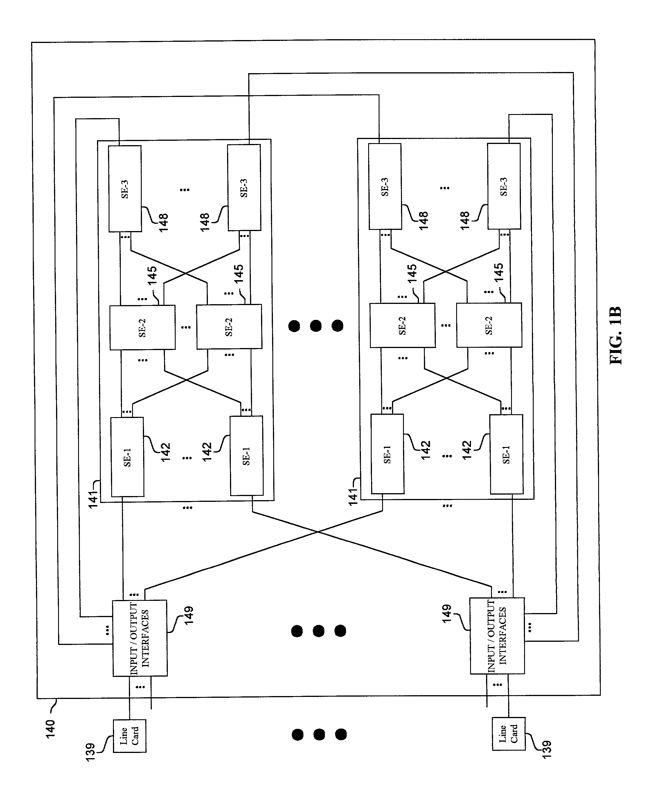
[0016]Methods and apparatus are disclosed for accumulating, distributing and reacting to detected faults and other error conditions in a packet switching system. Such methods and apparatus are not limited to a single packet switching environment. Rather, the architecture and functionality taught herein are extensible to an unlimited number of packet switching environments and embodiments in keeping with the scope and spirit of the invention. Embodiments described herein include various elements and limitations, with no one element or limitation contemplated as being a critical element or limitation. Each of the claims individually recite an aspect of the teachings disclosed herein in its entirety. Moreover, some embodiments described may include, inter alia, systems, integrated circuit chips, methods, and computer-readable medium containing instructions. The embodiments described hereinafter embody various aspects and configurations within the scope and spirit of the invention.

[0017...


PUM


Abstract

Methods and apparatus are disclosed for distributing fault indications and maintaining and using a data structure indicating faults to route traffic in a packet switching system. In one embodiment, a packet switching system detects faults and propagates indications of these faults to the input interfaces of a packet switch, so the packet switch can adapt the selection of a route over which to send a particular packet. Faults are identified by various components of the packet switching system and relayed to one or more switching components to generate a broadcast packet destined for all input ports (i.e., to each I / O interface in a packet switch having folded input and output interfaces). Other embodiments, generate one or more multicast or unicast packets. The I / O interface maintains one or more data structures indicating the state of various portions of the packet switching system. In one embodiment, an output availability table is maintained indicating over which path a particular destination may be reached, as well as a link availability vector indicating which output likes of the input interface may be currently used. Using these as masks against possible routes in a fully functional system, the packet switching component (e.g., I / O interface) can identify which routes are currently available for reaching the destination of the received packet. These routes can then be selected between using one of numerous deterministic and non-deterministic methods.

Description

FIELD OF THE INVENTION[0001]This invention relates to maintaining, communicating, and reacting to faults in packet switching systems; and more particularly, the invention relates to distributing fault indications and maintaining and using a data structure indicating faults used to route traffic through a packet switching system.BACKGROUND OF THE INVENTION[0002]The communications industry is rapidly changing to adjust to emerging technologies and ever increasing customer demand. This customer demand for new applications and increased performance of existing applications is driving communications network and system providers to employ networks and systems having greater speed and capacity (e.g., greater bandwidth). In trying to achieve these goals, a common approach taken by many communications providers is to use packet switching technology.[0003]As used herein, the term “packet” refers to packets of all types, including, but not limited to, fixed length cells and variable length pac...

Claims


Application Information

Patent Timeline
Patent Type & Authority Patents(United States)
IPC IPC(8): G01R31/08H04Q11/00
CPCH04Q3/68H04L49/55H04L49/1523
Inventor LENOSKI, DANIEL E.EATHERTON, WILLIAM N.FINGERHUT, JOHN ANDREWTURNER, JONATHAN S.
Owner CISCO TECH INC
Learn More