
Pothole repair machine

a pothole repair machine and pothole technology, applied in the field of machines, can solve the problems of inability to bond with the existing adjacent, inability to provide efficient operability and economically affordable pothole repair systems, and inability to provide the consistent repair of potholes in the manner of prior art pothole repair machines, etc., to achieve carefree maintenance, low manufacturing cost, and durable construction

Inactive Publication Date: 2006-01-24
ZIMMERMAN HAROLD M
View PDF11 Cites 29 Cited by
  • Summary
  • Abstract
  • Description
  • Claims
  • Application Information

AI Technical Summary

Benefits of technology

[0008]It is another object of this invention to provide a pothole repair machine that provides a cost effective process for the repair of potholes in roadway surfaces.
[0019]It is yet another object of this invention to provide a pothole repair machine that is durable in construction, inexpensive of manufacture, carefree of maintenance, facile in assemblage, and simple and effective in use.

Problems solved by technology

Such cold patch asphalt paving material is typically utilized in cold weather installations and suffers from the limitation of not being able to bond with the existing adjacent, contiguous paving material to enable the patch material to remain in place.
Thus, pothole repairs accomplished in this manner are often temporary.
Such prior art pothole repair machines have not been configured to provide an efficiently operable and economically affordable system for the consistent repair of potholes.
The Blaha machine, for example, is a large cumbersome apparatus in which the process is attempted to be automated.
The Dillingham cart, on the other hand, is too small to be efficient in the repair of a large quantity of potholes.
Cold patch pothole repair machines cannot provide a lasting repair, even with the utilization of a tack coat before the filling material is added to the pothole.
Potholes are not formed in a regular uniform manner and uniformity cannot be relied upon in formulating a process to effect their repair.

Method used


Image

  • Pothole repair machine
  • Pothole repair machine
  • Pothole repair machine

Examples


Embodiment Construction

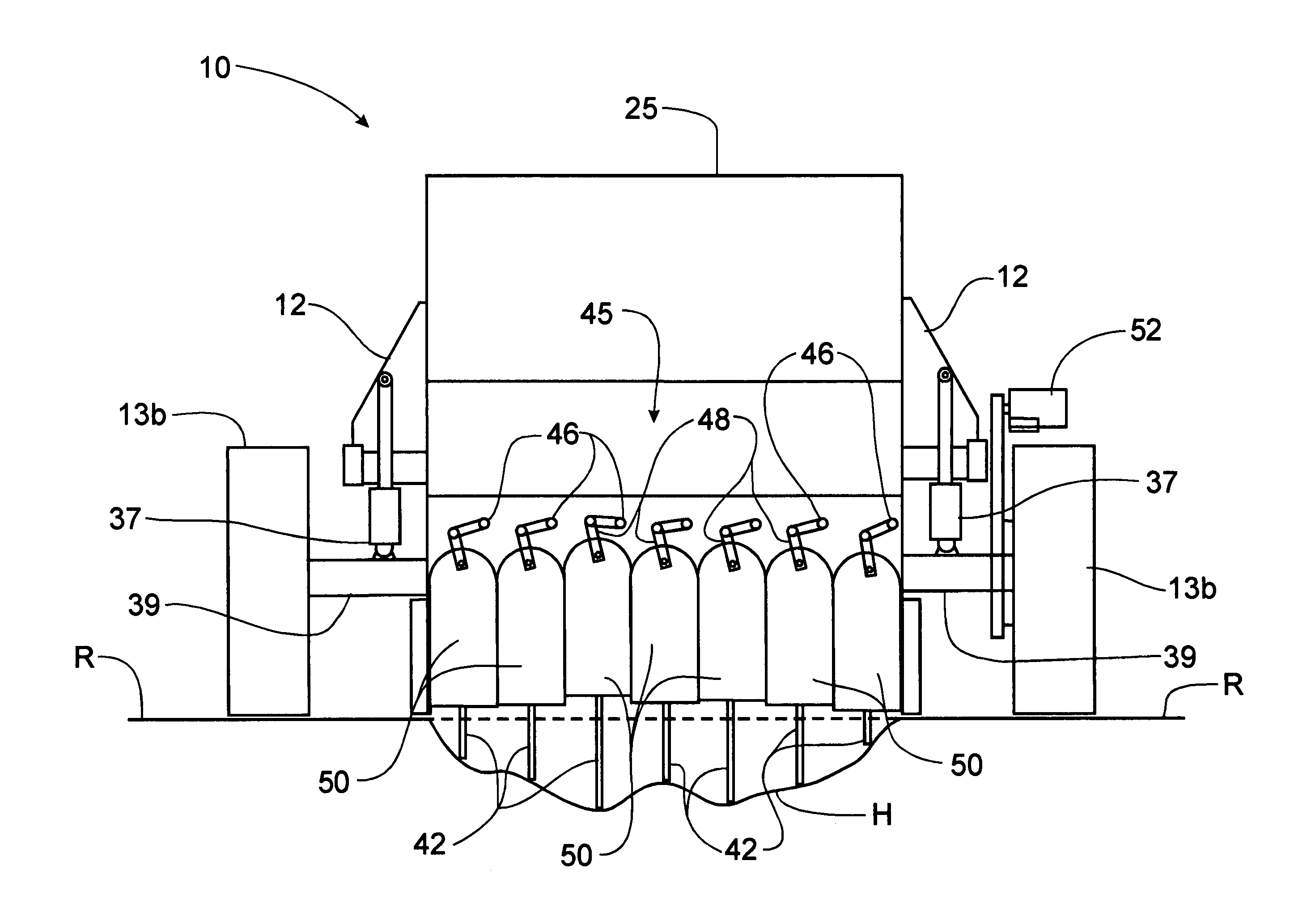
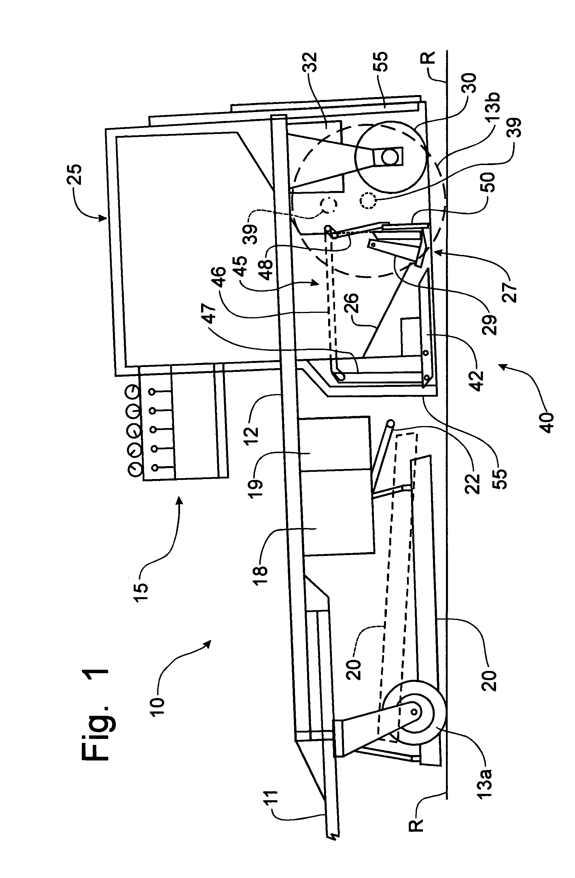
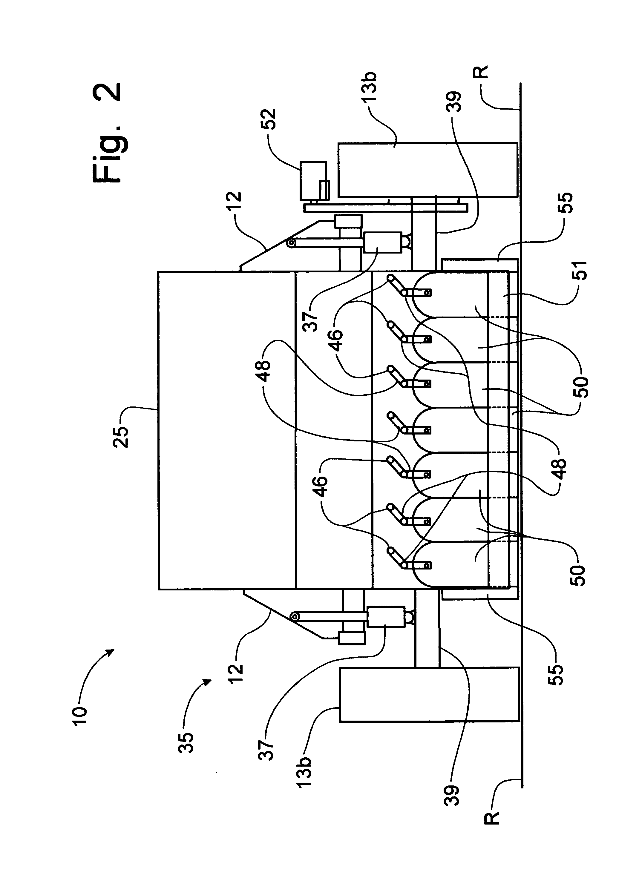
[0026]Referring to the drawings, a pothole repair machine incorporating the principles of the instant invention can best be seen. The machine 10 is preferably a towed implement that can be attached to a pick-up truck (not shown) or a highway truck (not shown) by a trailer hitch 11 to be moved from one location to another. In the alternative, the machine 10 could be a self-propelled apparatus in which an engine is operatively mounted on the machine 10 to provide operative and motive power. The machine 10 includes a frame 12 supported above the ground by a pair of front wheels 13a and a pair of rear wheels 13b. The frame 12 also supports a heated material hopper 25 for holding a supply of hot mix asphalt material. Manually operable controls 15 are associated with a hydraulic system (not shown) to control the operation of the various functions to be described and defined in greater detail below. The frame 12 also supports additional reservoirs 18, 19 for heated asphalt tack coat spray ...


PUM


Abstract

A pothole repair machine utilizes hot mix asphalt material to fill the pothole being repaired. The machine includes a heating apparatus for raising the temperature of the surface of the road surrounding the pothole to soften the material for bonding with the material to be inserted into the pothole. A hot tack spray is then placed onto the surface of the pothole before hot mix material is deposited into the pothole cavity. Before depositing the hot mix material, a sensing mechanism determines the depth of the pothole and causes an adjustment of the height of screening doors to effect the uncompressed height of the filling material at a predetermined percentage of overfill before a vibrating roller compresses the filling material to the level of the surrounding roadway. A plurality of screening doors extends along the transverse width of the machine, each door being adjustably controlled by a depth sensor member.

Description

BACKGROUND OF THE INVENTION[0001]The present invention is directed to machines for laying asphalt paving material and, more particularly, to a machine for repairing potholes in paved road surfaces.[0002]Machines for repairing potholes are known in the art; however, most known pothole repair machines, such as is shown in U.S. Pat. No. 5,131,788, issued to Leslie Huliesko on Jul. 21, 1992; in U.S. Pat. No. 5,294,210, issued to Jerome Lemelson on Mar. 15, 1994; and in U.S. Pat. No. 5,752,782, issued to Leslie Huliesko on May 19, 1998, are designed to dispense a cold patch material in which the asphalt paving material is combined with an emulsion to provide a plastic paving material that will harden when placed into the environment. Such cold patch asphalt paving material is typically utilized in cold weather installations and suffers from the limitation of not being able to bond with the existing adjacent, contiguous paving material to enable the patch material to remain in place. Thus...

Claims


Application Information

Patent Timeline
Patent Type & Authority Patents(United States)
IPC IPC(8): E01C23/14
CPCE01C23/07E01C23/06
Inventor ZIMMERMAN, HAROLD M.
Owner ZIMMERMAN HAROLD M
Learn More