Simplified ocular fundus auto imager

Inactive Publication Date: 2008-04-22
VISUAL PATHWAYS
View PDF69 Cites 20 Cited by
  • Summary
  • Abstract
  • Description
  • Claims
  • Application Information

AI Technical Summary

Benefits of technology

[0010]The present invention is in the nature of a fundus camera which automatically and quickly performs all the aligning and focusing functions. As a result, any unskilled person can learn to obtain high quality images after only a few minutes of training and the entire imaging procedure requires far less time than existing fundus cameras. Moreover, all of the automatic aligning and focusing procedures are performed using barely visible infrared illumination. With such illumination, the patient's pupils do not constrict and for all but patients with unusually small natural pupils, no artificial dilation is required. The fundus images can be obtained under infrared illumination and are acceptable for many purposes so that the patient need not be subjected to the extremely bright flashes required for existing fundus cameras. To obtain standard color images using the present invention, it is sometimes necessary to illuminate the eye with flashes of visible light. Howeve

Problems solved by technology

However, to use existing fundus cameras successfully is a very difficult undertaking.
Therefore, the use of existing fundus cameras requires a significant amount of training and skill; even the most skilled opera

Method used


Image

  • Simplified ocular fundus auto imager
  • Simplified ocular fundus auto imager
  • Simplified ocular fundus auto imager

Examples


Embodiment Construction

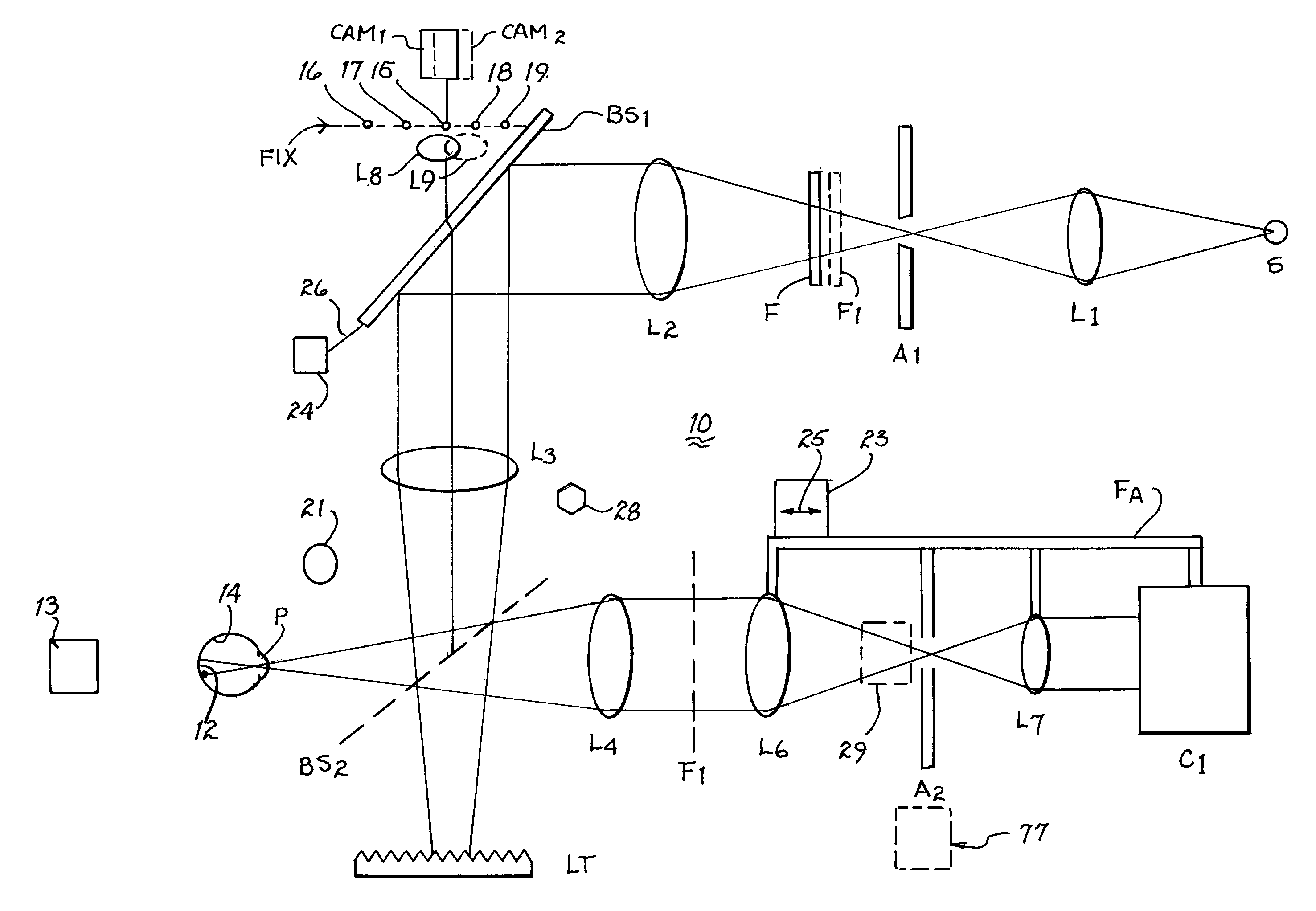
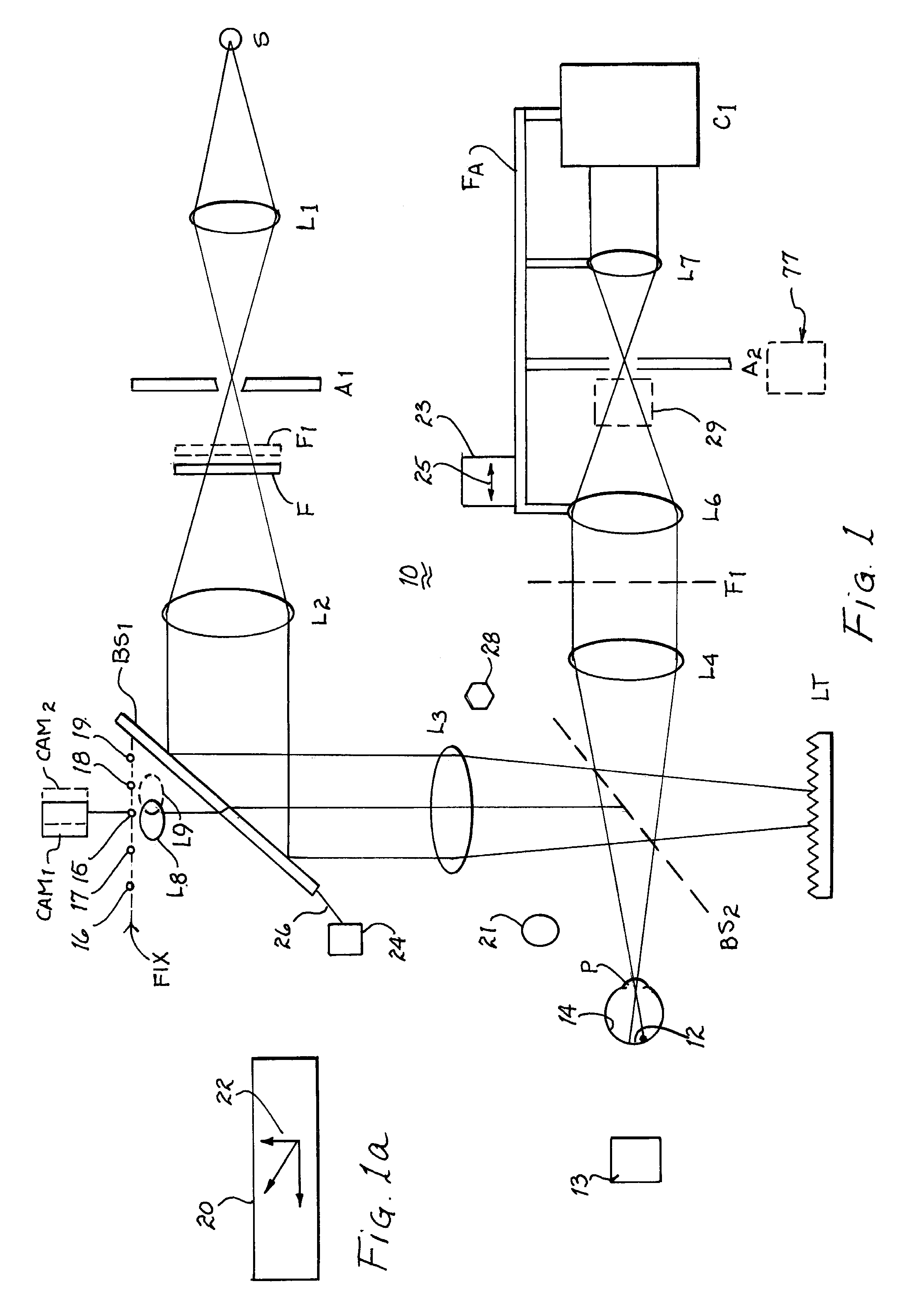
[0038]Referring to FIG. 1, there is illustrated a preferred embodiment of optical system 10 of the present invention. Lens L1 focuses light from a light source S onto a small aperture A1. The light source may be a source of visible light, infrared radiation or of a wavelength in the near visible infrared region. Light passing through aperture A1 passes through a filter F toward lens L2. Lens L2 collimates (makes parallel) light from aperture A1. A beam splitter BS1 reflects about ninety percent (90%) of the incident light from lens L2 to lens L3. Half of the light passing through lens L3 is transmitted through beam splitter BS2 and is absorbed by light trap LT. The other half of the light passing through lens L3 is reflected by beam splitter BS2 and forms an image of aperture A1 in the focal plane of lens L3, which focal plane lies in the plane of a patient's pupil P. The light passing through the pupil illuminates a section 12 of ocular fundus 14 (hereinafter only the term fundus w...


PUM


Abstract

An ocular fundus imager automatically aligns fundus illuminating rays to enter the pupil and to prevent corneal reflections from obscuring the fundus image produced. Focusing the produced fundus image is automatically performed using a pair of video sensors and is based upon the fundus image itself. A head restraint is used to reduce the gross alignment between the optical system and the patient's pupil.

Description

CROSS REFERENCE TO RELATED APPLICATIONS[0001]The present application is a continuation-in-part application of an application entitled “Ocular Fundus Auto Imager”, filed Dec. 16, 2002, assigned Ser. No. 10 / 311,492, now U.S. Pat. Ser. No. 7,025,459 which is a national phase application based on a Patent Cooperation Treaty application entitled “Ocular Fundus Auto Imager”, filed Jul. 6, 2001, assigned Ser. No. PCT / US01 / 21410, which is a continuation of and claims priority to a United States application entitled “Ocular Fundus Auto Imager”, filed Aug. 25, 2000, assigned Ser. No. 09 / 649,462, now U.S. Pat. No. 6,296,358 and which application claims priority to the subject matter disclosed in a provisional application entitled “FUNDUS AUTO IMAGER”, filed Jul. 17, 2000 and assigned Ser. No. 60 / 218,757 all of which applications are directed to an invention made by the present inventors and assigned to the present assignee.BACKGROUND OF THE INVENTION[0002]1. Field of the Invention[0003]The pre...

Claims


Application Information

Patent Timeline
IPC IPC(8): A61B3/14A61B3/12A61B3/15
CPCA61B3/12A61B3/156
Inventor CORNSWEET, TOM N.BUCK, GARY F.PETERSON, PAUL R.
Owner VISUAL PATHWAYS
Why Eureka
Try Eureka