Brightness adjusting apparatus for stereoscopic camera
a stereoscopic camera and brightness adjustment technology, applied in the field of brightness adjustment apparatus for stereoscopic cameras, can solve the problems of deviating gradually from the initial set value, affecting the accuracy of stereo matching, and affecting so as to improve the accuracy of monitoring around the vehicle.
- Summary
- Abstract
- Description
- Claims
- Application Information
AI Technical Summary
Benefits of technology
Problems solved by technology
Method used
Image
Examples
first embodiment
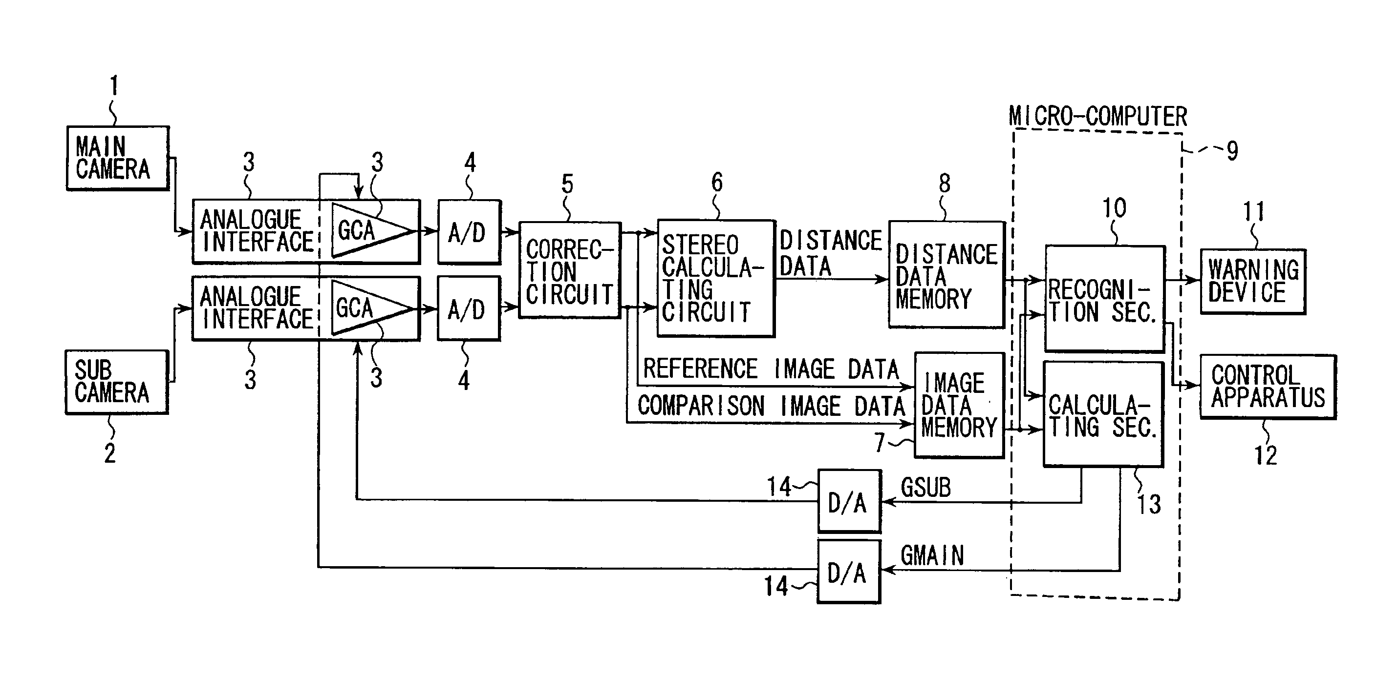
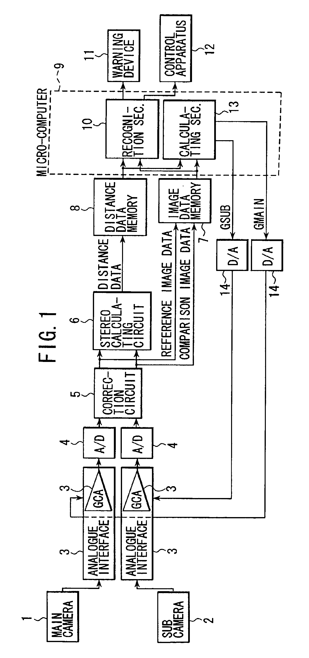
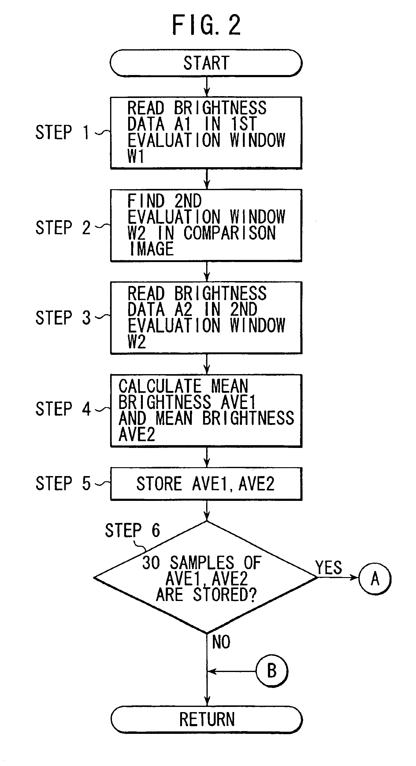
[0020]An operation will be described. A calculation section 13 of the micro-computer 9 performs a feed-back adjustment of a gain of the gain control amplifier 3a according to the flowcharts shown in FIGS. 2 and 3. These flowcharts are carried out repeatedly in every cycle of a specified time interval. The calculation section 13 calculates a main gain indicating value GMAIN for the main camera 1 and a sub gain indicating value GSUB for the sub camera 2, these values are converted into analogue values by D / A converters 14, 14 respectively and the converted analogue signals are inputted to the respective gain control amplifiers 3a, 3a.
[0021]First, at a step 1, a brightness data A1 of each pixel existing in a first evaluation window W1 established in the reference image is read. FIG. 4 is a diagram for explaining the establishment of the first evaluation window W1 and a second evaluation window W2 which will be described hereinafter. The first evaluation window W1 is constituted by 16...
second embodiment
[0042]FIG. 7 is a flowchart showing a process for adjusting a gain according to the present invention.
[0043]In the flowchart, first at a step 21, brightness data A1 of sub zones R1, R2, R3 (hereinafter, referred to as first zones) constituting the first evaluation window W1 in the reference image are read. Further, at a step 22, brightness data A2 of sub zones R4, R5, R6 (hereinafter, referred to as second zones) constituting the second evaluation window W2 in the comparison image are read.
[0044]FIG. 8 is a diagram for explaining the establishment position of the first evaluation window W1 and the second evaluation window W2. The first zones R1, R2 and R3 positionally correspond to the second zones R4, R5 and R6, respectively. The positions of R4, R5 and R6 of the second zones are established, in consideration of the stereo matching, being offset slightly from the positions R1, R2 and R3 of the first zones in the direction of the stereo matching. The offset amount is established tak...
PUM
 Abstract
Description
Claims
Application Information
 - Generate Ideas
- Intellectual Property
- Life Sciences
- Materials
- Tech Scout
- Unparalleled Data Quality
- Higher Quality Content
- 60% Fewer Hallucinations
Browse by: Latest US Patents, China's latest patents, Technical Efficacy Thesaurus, Application Domain, Technology Topic, Popular Technical Reports.
© 2025 PatSnap. All rights reserved.Legal|Privacy policy|Modern Slavery Act Transparency Statement|Sitemap|About US| Contact US: help@patsnap.com


