Rotary conveyor with fingers

Inactive Publication Date: 2006-01-17
DEERE & CO
View PDF16 Cites 18 Cited by
  • Summary
  • Abstract
  • Description
  • Claims
  • Application Information

AI Technical Summary

Benefits of technology

[0008]It is an object of the present invention to provide a drum conveyor of simple construction that can be provided with a large number of fingers.
[0010]Owing to the fact that several finger supports with different rotation angles are associated with one position of the axle, the number of fingers that can be attached to the axle can be increased with little complexity and expense. This improves the conveying action of the rotary conveyor.
[0012]The finger supports can be arranged offset from one another in the axial direction. This makes it possible to use finger supports of the same type, which is advantageous from the standpoint of production and storage; owing to their axial offset, they can be mounted on the axle at various points. As a rule, the fingers are then also offset in the axial direction. If respective groups of fingers are to have the same axial position, then similar axially offset finger supports can be used which have several finger attachment points offset in the axial direction, with only some of the said attachment points actually fitted with fingers. Alternatively, different finger supports or ones fitted on the axle in the reverse direction are used, such that the fingers of one group all adopt the same axial position.
[0014]To reduce the number of structural elements making up the rotary conveyor, the length of the finger supports can be chosen such that they extend essentially over the full width of the shell (or the portion of it provided with fingers). It is also conceivable, however, to arrange several shorter finger supports axially next to one another.
[0016]The rotary conveyor of the present invention, is particularly suitable for agricultural use. It can be used with the harvesting platforms of combine harvesters to convey the harvested crop into a feeder house. It can also be used above the straw walkers of a harvester to improve the separation of residual grains.

Problems solved by technology

The arrangement disclosed in U.S. Pat. No. 675,418 A allows a larger number of fingers, but has the disadvantage that replacement of a holder that has become defective entails dismantling the conveyor completely, which is a very time-consuming and therefore expensive process.
In GB 612 962 A fingers are also arranged in a star, but almost every finger is associated with its own rotating attachment to the holder also fitted onto and pivoting around the axle, which results in a relatively expensive structure.

Method used


Image

  • Rotary conveyor with fingers
  • Rotary conveyor with fingers
  • Rotary conveyor with fingers

Examples


Embodiment Construction

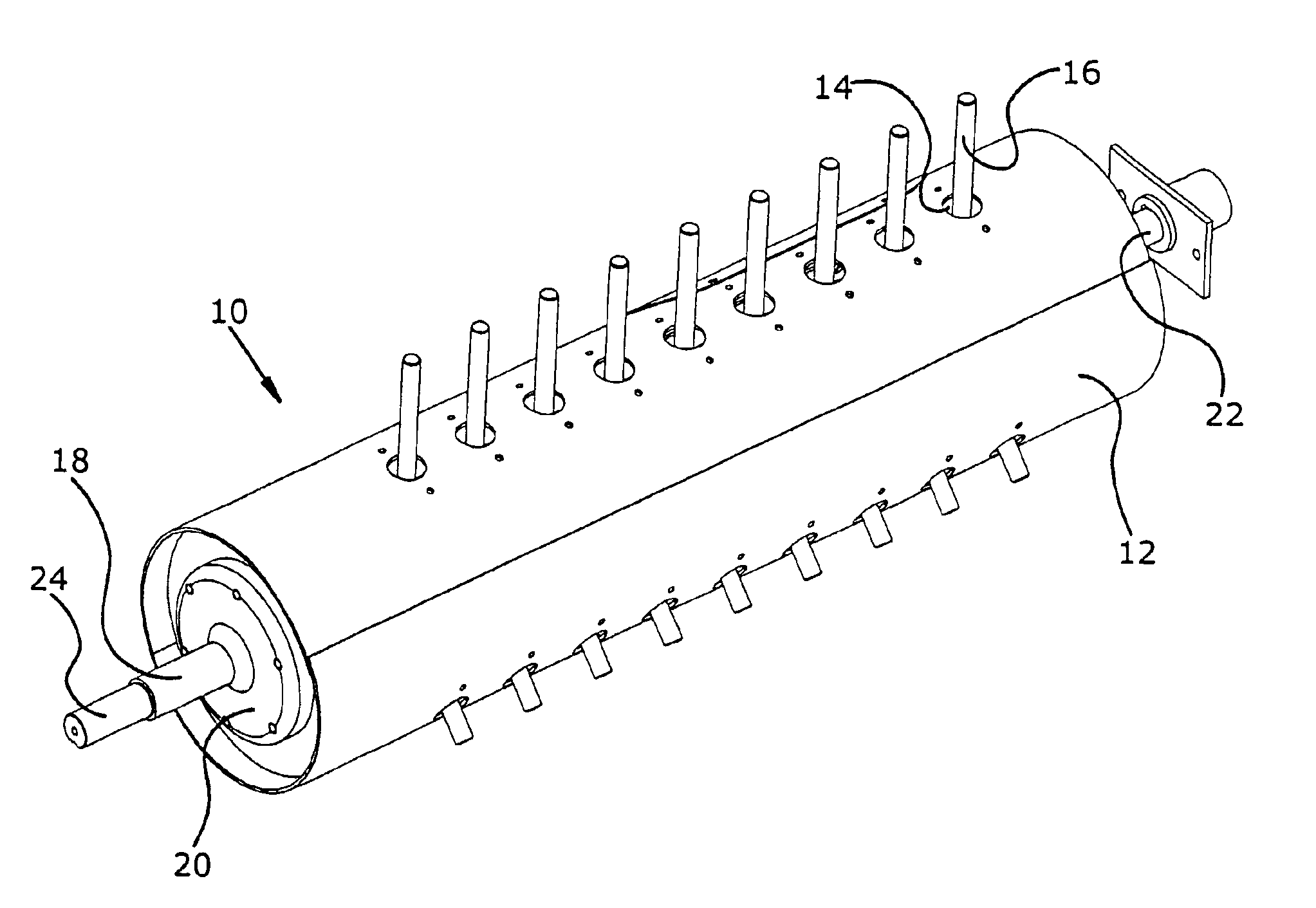
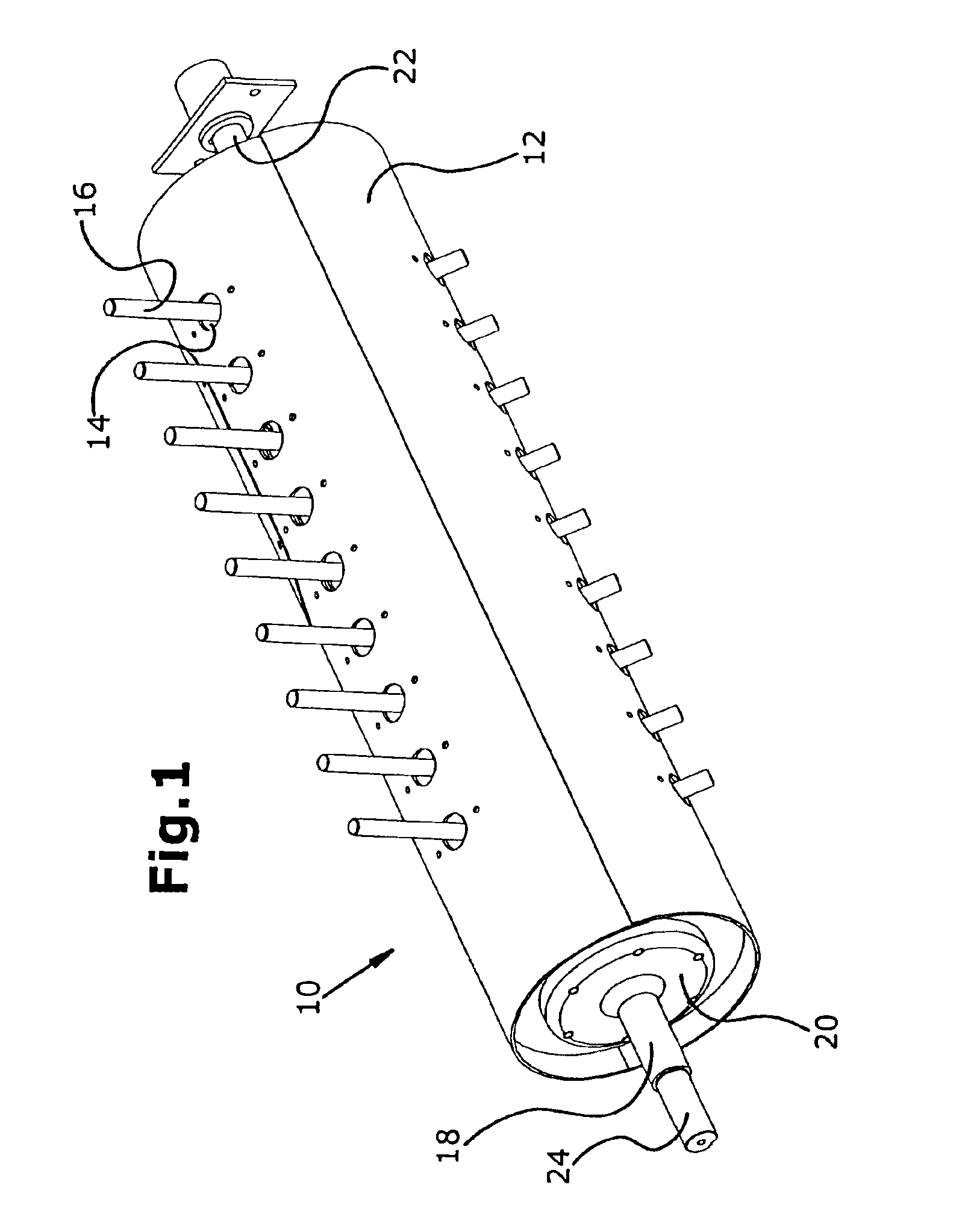
[0021]The rotary conveyor 10 shown in FIG. 1 comprises a drum-shaped shell 12 over whose length and circumference are distributed three rows of openings 14 offset by 120° relative to one another, through which extend fingers 16. Slide bearings 46 for the fingers 16 can be set into the openings (see FIG. 4), which are not shown inFIG. 1 for the sake of simplicity. The shell 12 can be made to rotate in order to convey material, by a drive system (not shown in FIG. 1) that engages a hollow shaft 18 connected to a flange 20 of the shell 12 with which it rotates. A first axle end 22 on the right of the rotary conveyor 10 is supported by and rotates on a housing. In an identical manner, a second axle end 24 positioned inside the hollow shaft 18 is supported by and rotates on a housing, not shown.

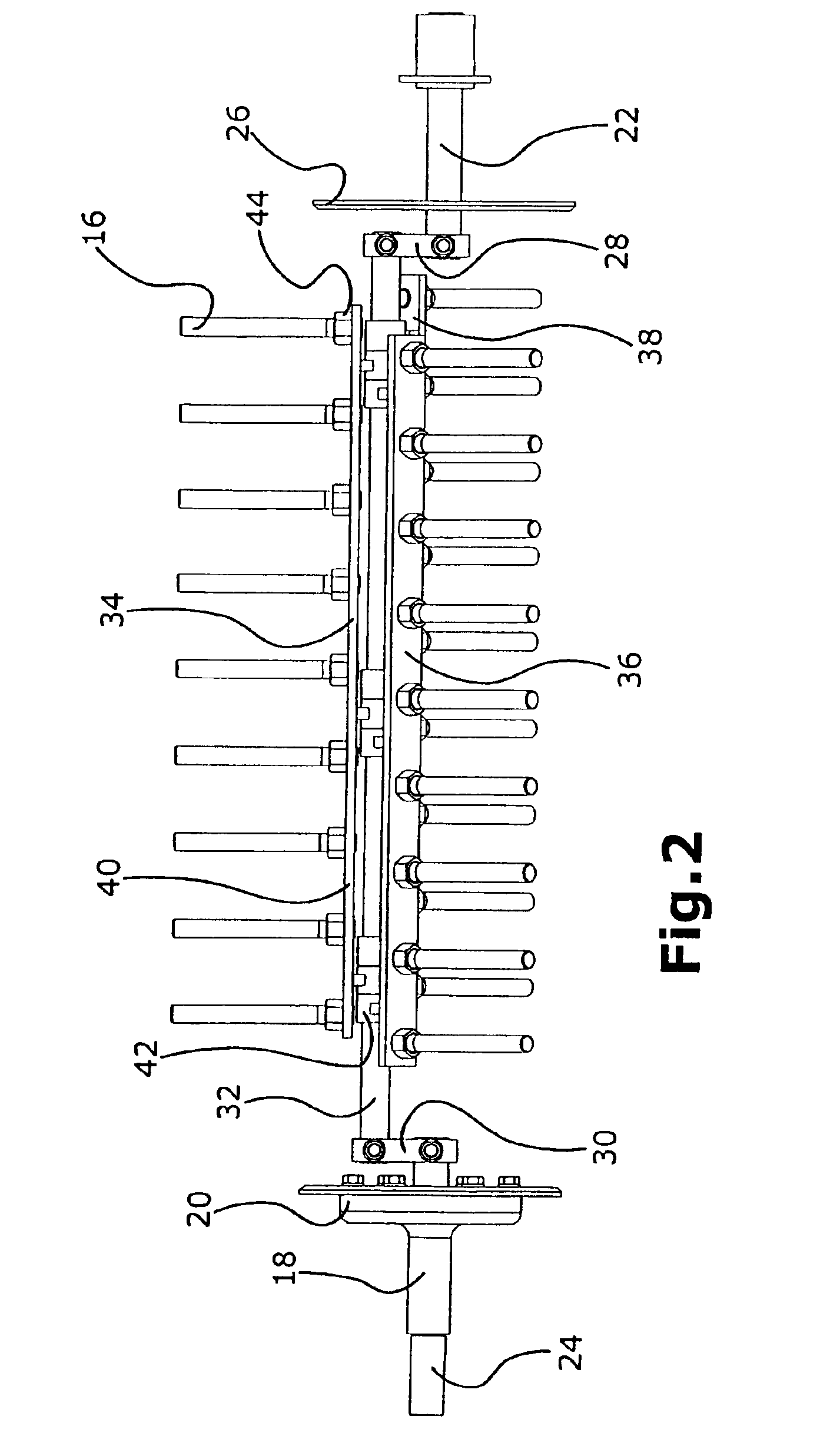
[0022]As illustrated in FIG. 2, the right edge of the shell 12 is supported on a disc 26 that is rotatively mounted on the first axle end 22. The left edge of the shell 12 is supported on flange 2...


PUM


Abstract

A rotary conveyor comprises a rotatable drum-shaped shell, an eccentric axle located in the drum-shaped shell, finger supports mounted to the eccentric axle, and a plurality of fingers mounted to the finger supports that extend outwardly through openings in the drum-shaped shell. The finger supports are rotatively mounted to and spaced radially outward from the eccentric axle by annular bearings. The finger supports are parallel to the eccentric axle and are provided with a plurality of fingers, such that several fingers arranged next to one another in the axial direction are attached to finger supports. The finger supports are distributed around the circumference of the eccentric axle.

Description

FIELD OF THE INVENTION[0001]The present invention is directed to a rotary conveyor comprising a rotatable drum-shaped shell, a stationary eccentric axle arranged inside the shell, and a plurality of fingers arranged on finger supports that are rotatively mounted to the eccentric axle. The fingers extend through openings in the shell, such that several fingers are arranged next to one another in the axial direction.BACKGROUND OF THE INVENTION[0002]U.S. Pat. No. 675,418 A discloses a rotary conveyor having a drum-shaped shell with fingers extending through openings in the shell. The fingers are mounted and can rotate on an eccentric, fixed axle, so that the length by which the fingers project out of the shell depends on the rotation position of the rotating shell which carries the fingers along with it as it turns. On the axle, four groups of fingers are arranged axially alongside one another, each group having three fingers, one of which in each case passes through one of three openi...

Claims


Application Information

Patent Timeline
IPC IPC(8): A01D89/00A01D61/00
CPCA01D89/002A01D61/008
Inventor BECK, FOLKER
Owner DEERE & CO
Why Eureka
Try Eureka