
Prevention of unwanted material accumulations

a technology for unwanted materials and accumulations, applied in the direction of valve housings, container discharge methods, functional valve types, etc., can solve the problems of affecting the chemical process industry on a daily basis, limiting process flow, and initiating undesirable side reactions

Active Publication Date: 2006-01-10
ROHM & HAAS CO
View PDF8 Cites 26 Cited by
  • Summary
  • Abstract
  • Description
  • Claims
  • Application Information

AI Technical Summary

Problems solved by technology

The accumulation of unwanted material in low flow regions of process equipment is a problem which adversely affects the chemical process industries on a daily basis.
Unwanted materials may restrict process flows, initiate undesirable side reactions (such as stress corrosion cracking), seed polymer growth, and render secondary process devices—such as valves and instrumentation—inoperable.
The accumulation of unwanted material is costly in that it requires process downtime and manpower to remove these materials and to repair associated damage to the process equipment and piping that may have occurred.
In addition, hazardous situations can result when safety equipment, such as pressure relief devices, are isolated from the process through the accumulation of unwanted materials in the process connections to which they are attached.
This approach is ineffective, however, in low flow regions such as process connections where the monomer vapors can stagnate and become trapped; this situation is further exacerbated when the process connection is a vessel nozzle, oriented vertically on the top head of the process equipment in question.
Because low flow regions, such as nozzles, are essentially stagnant, however, vapor-phase inhibitors tend not to flow into them and unwanted material accumulation can proceed essentially unabated.
This approach fails to adequately prevent the simultaneous accumulation of material in small, low-flow regions, such as the process connections on the top heads of tanks and columns.
The installation of the spray nozzle is mechanically complex as well as invasive to the vessel, requiring a separate vessel penetration (not shown) and the positioning of the line(s) inside the vessel for supplying the liquid to the spray nozzle.
With this approach, the elevation and alignment of the spray nozzle itself, as well as the flow rate and spray pattern, are critical and, in practice, it is quite difficult to obtain the proper combination of these variables such that polymer accumulation is wholly prevented.
While the effectiveness of such an arrangement could be improved through the use of multiple spray nozzle and an overwhelmingly large quantity of liquid spray, such an approach is costly and impractical in commercial operations.
Additionally, the physical presence of the spray nozzle(s) and its supply line(s) create an undesirable obstruction in the process connection, thereby interfering with the free flow of material through the attached relief device, and these components themselves also create new surfaces for the accumulation of condensation polymer!
In some instances the direct impingement of pressurized spray liquid on the relief device may also cause mechanical fatigue, thereby shortening the service life of the rupture disk.
Because of these limitations, the proposed process for inhibiting polymerization is impractical when applied to the small, low flow regions associated with process connections, such as relief lines.
Yet despite familiarity with the needs of the chemical process industries, those skilled in the art of designing sight glass spray rings have not anticipated the use of such devices for the prevention o unwanted material accumulation in low flow zones such as process connections.
This need is especially great in the case where safety relief systems are attached to process connections comprising low flow regions; the accumulation of unwanted material in these nozzles restricting the free flow of material through the nozzle when the relief device is called upon to operate, thereby limiting the capacity of the relief device and creating an unsafe condition.

Method used


Image

  • Prevention of unwanted material accumulations
  • Prevention of unwanted material accumulations
  • Prevention of unwanted material accumulations

Examples


example

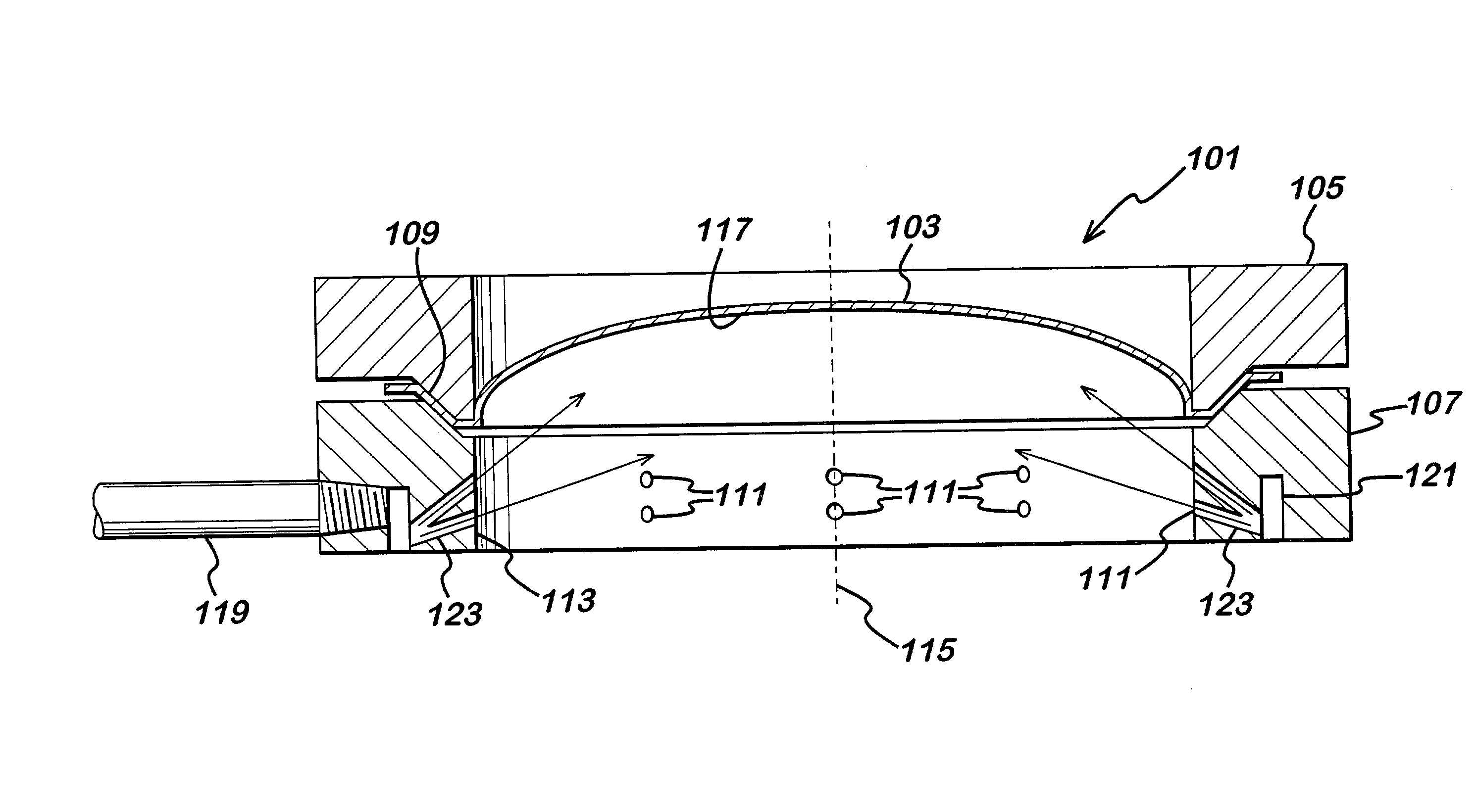
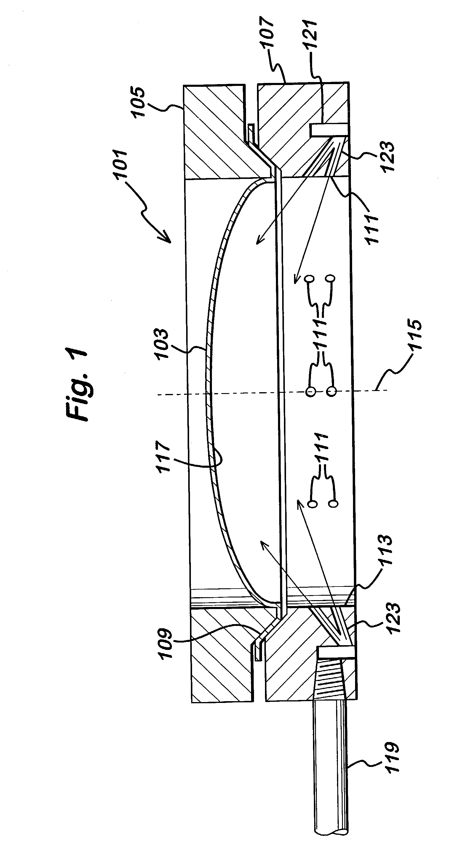
[0046]A flush ring is placed adjacent to the rupture disk holder on the 8-inch diameter top process connection nozzle of an acrylic acid distillation column in the manner as shown in FIG. 3. A 316-teflon-316 composite rupture disk (available from Continental Disc Corp.) was installed in the holder. The flush ring had an internal diameter 7½ inches and comprised two sets of fluid ports. The first set of ports comprises 8 equally spaced 3 / 32-inch diameter ports set at an angle of between 45 and 90 degrees relative to the axis of the ring. The second set of ports comprises 8 equally spaced 3 / 32-inch diameter ports set at an angle between 0 and 45 degrees relative to the axis of the ring. The flushing ring further comprises an open distribution channel which is sealed upon installation against a standard gasket flange. After installation, a flushing fluid is introduced through the ring which facilitates the removal of condensed polymerizable acrylic acid monomer from the upstream (lower...


PUM


Abstract

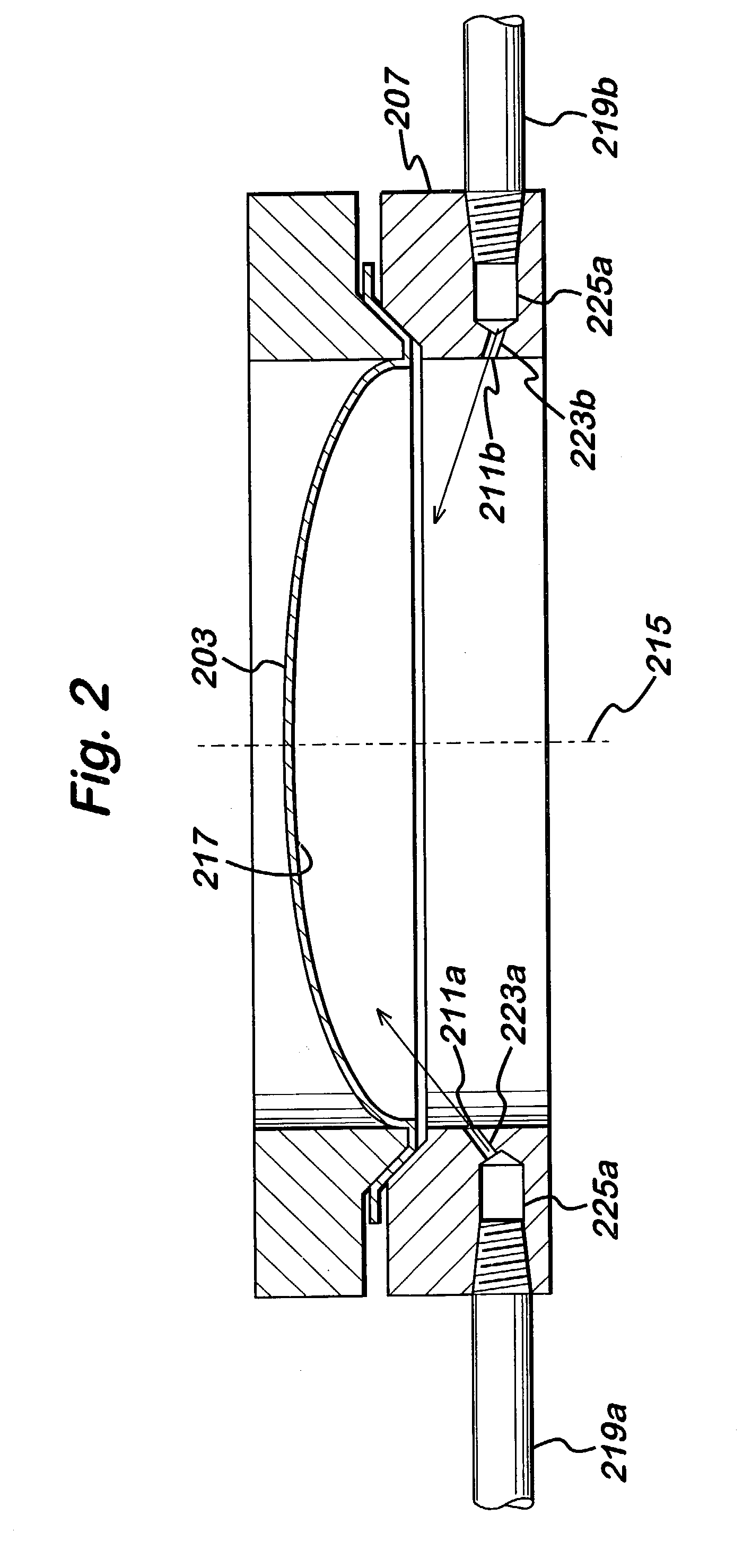
In one embodiment, the invention provides a rupture disk assembly having a rupture disk and a rupture disk holder. The rupture disk holder has a first annular member downstream of the rupture disk, a second annular member upstream of the rupture disk, and an optional third annular member upstream of the second annular member. An outer peripheral portion of the rupture disk is sandwiched between the first and second annular members; and, if a third annular member is present, (a) the second annular member is sandwiched between the outer peripheral portion of the rupture disk and the third annular member, and (b) the third annular member includes a fluid port aimed at the rupture disk. However, if the third annular member is not present, the second annular member includes a fluid port aimed at the rupture disk. In another embodiment, the invention provides an equipment access assembly having an equipment access cover, an equipment access cover mount, and an annular member between the equipment access cover and cover mount. The annular member includes a fluid port aimed at the equipment access cover. In yet another embodiment, the invention provides a valve mounting assembly having a downstream valve mount, an upstream valve mount, a valve intermediate the downstream and upstream valve mounts, and an annular member intermediate the valve and the upstream valve mount. The annular member includes a fluid port aimed at the valve.

Description

CROSS REFERENCE TO RELATED PATENT APPLICATIONS[0001]This is a non-provisional application of prior pending U.S. provisional application Ser. No. 60 / 394,011 filed Jul. 5, 2002.BACKGROUND OF THE INVENTION[0002]The accumulation of unwanted material in low flow regions of process equipment is a problem which adversely affects the chemical process industries on a daily basis. Unwanted materials may comprise by-products, residues, polymers, scale, dusts, corrosion products, precipitates, or other solids, liquids or vapors. Unwanted materials may restrict process flows, initiate undesirable side reactions (such as stress corrosion cracking), seed polymer growth, and render secondary process devices—such as valves and instrumentation—inoperable. The accumulation of unwanted material is costly in that it requires process downtime and manpower to remove these materials and to repair associated damage to the process equipment and piping that may have occurred. In addition, hazardous situations...

Claims


Application Information

Patent Timeline
IPC IPC(8): F16K17/40B65D90/36B01J19/00C08F2/01F16K17/00F16K17/16F16K27/00F16L55/24F17C13/06F17C13/12
CPCB08B5/02B08B17/06F16K27/00F16K17/16F16K17/00Y10T137/1714Y10T137/4259
Inventor DECOURCY, MICHAEL STANLEYWILLIAMS, CONNIE SUEWILLIAMS, DAVID ALEC
Owner ROHM & HAAS CO
Learn More