
Shaped charge explosive device and method of making same

a technology of explosive devices and shaped charges, which is applied in the field of explosive devices, can solve the problems of affecting the cost, ease of manufacture and transportation of such devices, and the inability of shapers to efficiently focus the energy of detonation waves into contact with the shaped charge liner, and achieve the effect of efficient focusing detonation waves

Inactive Publication Date: 2006-01-10
ARMY US SEC THE
View PDF14 Cites 20 Cited by
  • Summary
  • Abstract
  • Description
  • Claims
  • Application Information

AI Technical Summary

Benefits of technology

[0009]Accordingly, it is an object of the present invention to provide an improved shaped charge explosive device that efficiently focuses detonation waves.
[0010]Additionally, it is an object of the present invention to provide a shaped charge explosive device that generates an increased jet tip velocity and hypervelocity jet particles, resulting in improved penetration characteristics.
[0012]It is also an object of the present invention to provide a shaped charge explosive device that is cost-effective to produce and is easy to manufacture.
[0013]It is a further object of the present invention to provide a shaped charge explosive device which, while having higher penetrating capabilities than similar shaped charge explosive devices, requires a lower mass of explosive charge to achieve such results.
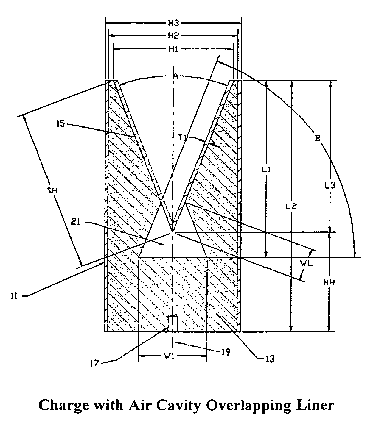
[0014]These and other objects of the invention are achieved in one aspect by a shaped charge explosive device which includes an axially symmetric body of explosive material, a liner lining the forward end of the body, and a detonator disposed at the rear end of the body. The liner has an apex disposed along the symmetry axis of the body and the forward end of the body contains a cavity which overlaps the apex of the liner. When the detonator detonates the explosive material, a detonation wave is produced that collapses the liner into a plurality of liner parts which are projected against an external target. The cavity shapes the detonation wave so that the detonation wave impacts the liner at the most favorable angle to transfer energy to the liner and maximize the effective penetration of the external target by the projected liner parts.
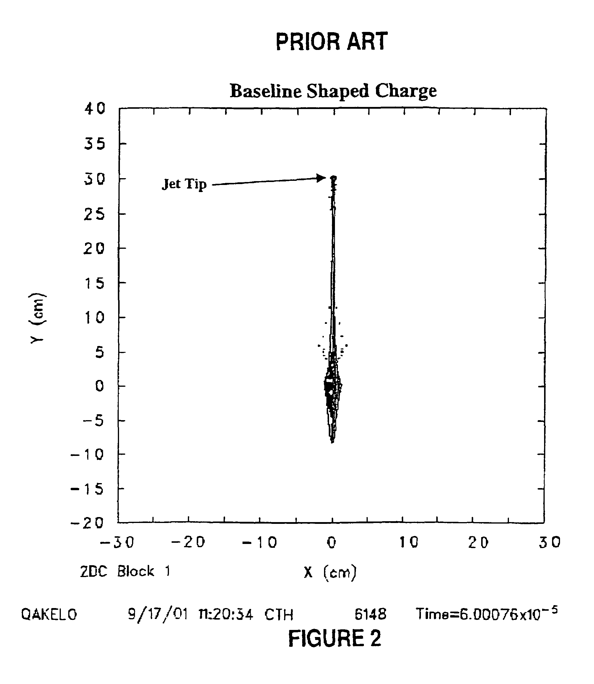
[0016]The shaped charge explosive device of the invention produces a jet with a higher tip velocity than a conventional round having the same or similar liner and other components. In addition to improved performance, hypervelocity jet particles of low mass preceding the main massive jet tip are generated. The production of such hypervelocity jet particles not only improves the effectiveness of the shaped charge explosive device of the invention in both military and industrial applications but also provides a means of simulating the behavior of micrometeorites in space which may be used to test the performance of the outer fuselage shells of spacecraft. Furthermore, smaller amounts of explosive charge are used to achieve the aforementioned improvements. In requiring a smaller explosive charge, the shaped charge explosive device is both less costly to produce and is more easily transported because of reduced weight. In addition, both casings (when employed) and liners of the shaped charge explosive devices of the invention typically are of conventional configurations and frequently uniform thicknesses, thereby simplifying production procedures and reducing associated costs.

Problems solved by technology

Most of these prior art techniques involve major modifications to the explosive device operation, ultimately affecting the cost, ease of manufacture and transport of such devices.
Although conventional wave shapers are useful in shaping the detonation wave from a purely divergent wave front, such wave shapers frequently do not efficiently focus the energy of the detonation wave into contact with the shaped charge liner.

Method used


Image

  • Shaped charge explosive device and method of making same
  • Shaped charge explosive device and method of making same
  • Shaped charge explosive device and method of making same

Examples


Embodiment Construction

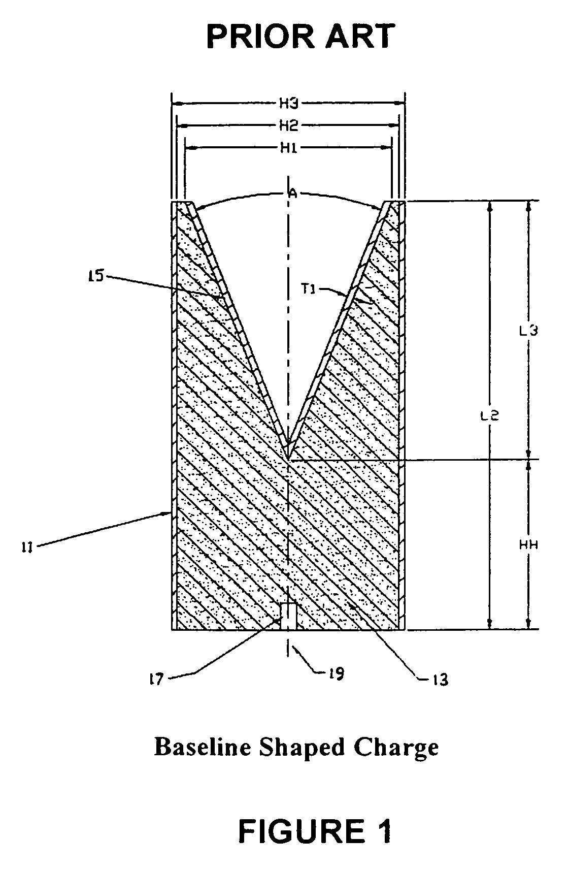
[0033]Referring to the drawings, where like reference numerals designate identical and corresponding parts, FIG. 1 shows a prior art shaped charge explosive device. The device has a casing 11 containing a body of explosive material 13, although as indicated above, shaped charge explosive devices of this type may be constructed without a casing when the explosive material is formed as a solid cake. In the device of FIG. 1, a regular right circular configuration is depicted as the preferred shape of the hollow cylinder casing 11 but other forms such as tapered or boat-tailed configurations have been employed. A liner 15, preferably a hollow conical insert with a thin wall although other arcuate geometries have been used depending on the desired result, is placed within the casing 11 above the body of explosive material 13, thereby disposing the explosive material between the casing 11 and the liner 15. A detonator 17 is located rearward and is shown as coaxial with the symmetry axis 1...


PUM


Abstract

A shaped charge explosive device which includes an axially symmetric body of explosive material, a liner lining the forward end of the body, and a detonator disposed at the bottom of the body. The liner has an apex disposed along the symmetry axis of the body and the forward end of the body contains a gas filled cavity which overlaps the apex of the liner. When the detonator detonates the explosive material, a detonation wave is produced that collapses the liner into a plurality of liner parts which are projected against an external target. The gas filled cavity shapes the detonation wave so that the detonation wave impacts the liner at the most favorable angle to transfer energy to the liner and maximize the effective penetration of the external target by the projected liner parts.

Description

BACKGROUND OF THE INVENTION[0001]This invention relates in general to ammunition and explosives and more particularly to a shaped charge explosive device.[0002]Explosives and explosive devices have widespread use in military, antipersonnel, civil engineering and geological exploration applications. A vast number of factors may be varied in the control and use of such explosives and explosive devices to achieve a particular result. These factors include, among others, the design and arrangement of the component parts of such devices and the selection of the materials employed therein.[0003]Shaped charge designs are frequently employed to provide a deep hole in a target material and to maximize crater volume. A shaped charge is usually a rotationally symmetric body of explosive material, which may be used alone or be positioned in a hollow charge casing. The charge is covered by an inverted conical liner made from a ductile metal and a detonator is located within the charge along its ...

Claims


Application Information

Patent Timeline
Patent Type & Authority Patents(United States)
IPC IPC(8): F42B1/00F42B1/02
CPCF42B1/024F42B1/02
Inventor WALTERS, WILLIAMSCHEFFLER, DANIEL R.
Owner ARMY US SEC THE
Learn More