
Electronic apparatus transmitting electronic mail including image information, a control apparatus, and a storage medium

a control apparatus and electronic mail technology, applied in the field of electronic mail transmission devices, can solve the problems of poor security of electronic mail, unrealistically impossible to exchange conventionally, and the inability to confirm at the receiving end that the received portrait and the sender of electronic mail are the same person

Inactive Publication Date: 2006-01-03
FUJITSU LTD
View PDF46 Cites 34 Cited by
  • Summary
  • Abstract
  • Description
  • Claims
  • Application Information

AI Technical Summary

Benefits of technology

[0014]Accordingly, it is a general object of the present invention to provide a novel and useful electronic apparatus, control apparatus and computer-readable storage medium, in which the problems described above are eliminated.
[0015]Another and more specific object of the present invention to provide an electronic apparatus, control apparatus and storage medium which can prevent a third person from copying an electronic mail and impersonating as another person, enable confirmation by a simple means that a sender of the electronic mail is the person himself, and enable the user to know the importance or summary of the contents of the received electronic mail to a certain extent before actually reading the received electronic mail.

Problems solved by technology

As a result, it is impossible to judge by a simple means whether or not a sender of the electronic mail is actually the person himself, thereby making the security of the electronic mail poor.
As a result, it has recently become possible to exchange data having a large size which was realistically impossible to exchange conventionally due to the limited communication speed.
However, as is the case of the electronic mail system proposed in the Japanese Laid-Open Patent Application No. 5-204795 described above, although the conventional proposed electronic mail system has the function of transmitting the electronic mail based on the symbol such as the portrait, it is impossible to confirm at the receiving end that the received portrait and the sender of the electronic mail are the same person.
For this reason, it is impossible to prevent a third person from improperly copying the image of the electronic mail and impersonating as another person.
In other words, there are problems in that there is no simple method of confirming that the sender of the electronic mail is the person himself, and that the security of the electronic mail is poor.
In addition, the conventional electronic mail system provides no means of simply comprehending the importance of the received electronic mail or the summary of the contents of the received electronic mail before reading the received electronic mail.
As a result, there are problems in that the user cannot know the importance and the contents of the summary of the received electronic mail until the user actually reads the received electronic mail, and that a so-called junk mail cannot be confirmed unless the junk mail is actually read.

Method used


Image

  • Electronic apparatus transmitting electronic mail including image information, a control apparatus, and a storage medium
  • Electronic apparatus transmitting electronic mail including image information, a control apparatus, and a storage medium
  • Electronic apparatus transmitting electronic mail including image information, a control apparatus, and a storage medium

Examples


first embodiment

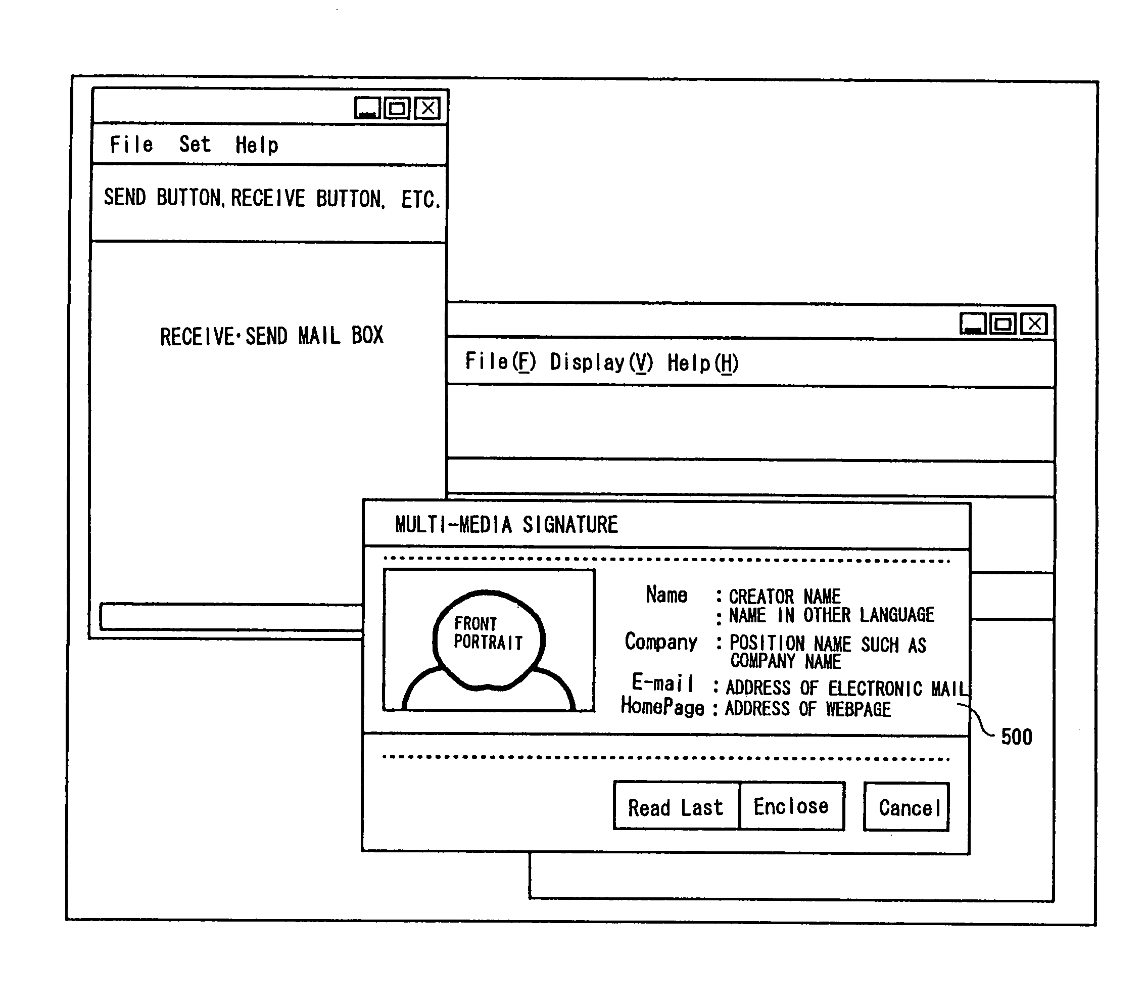
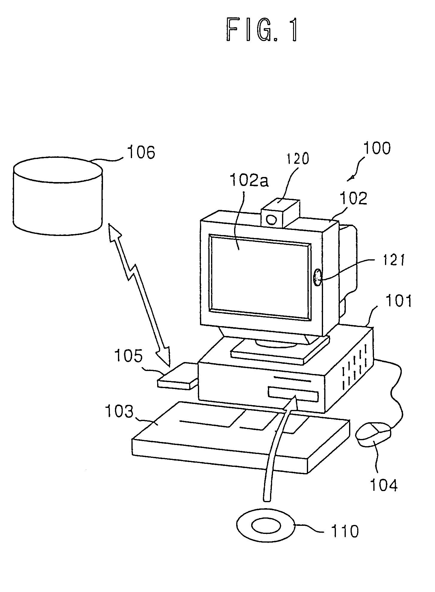
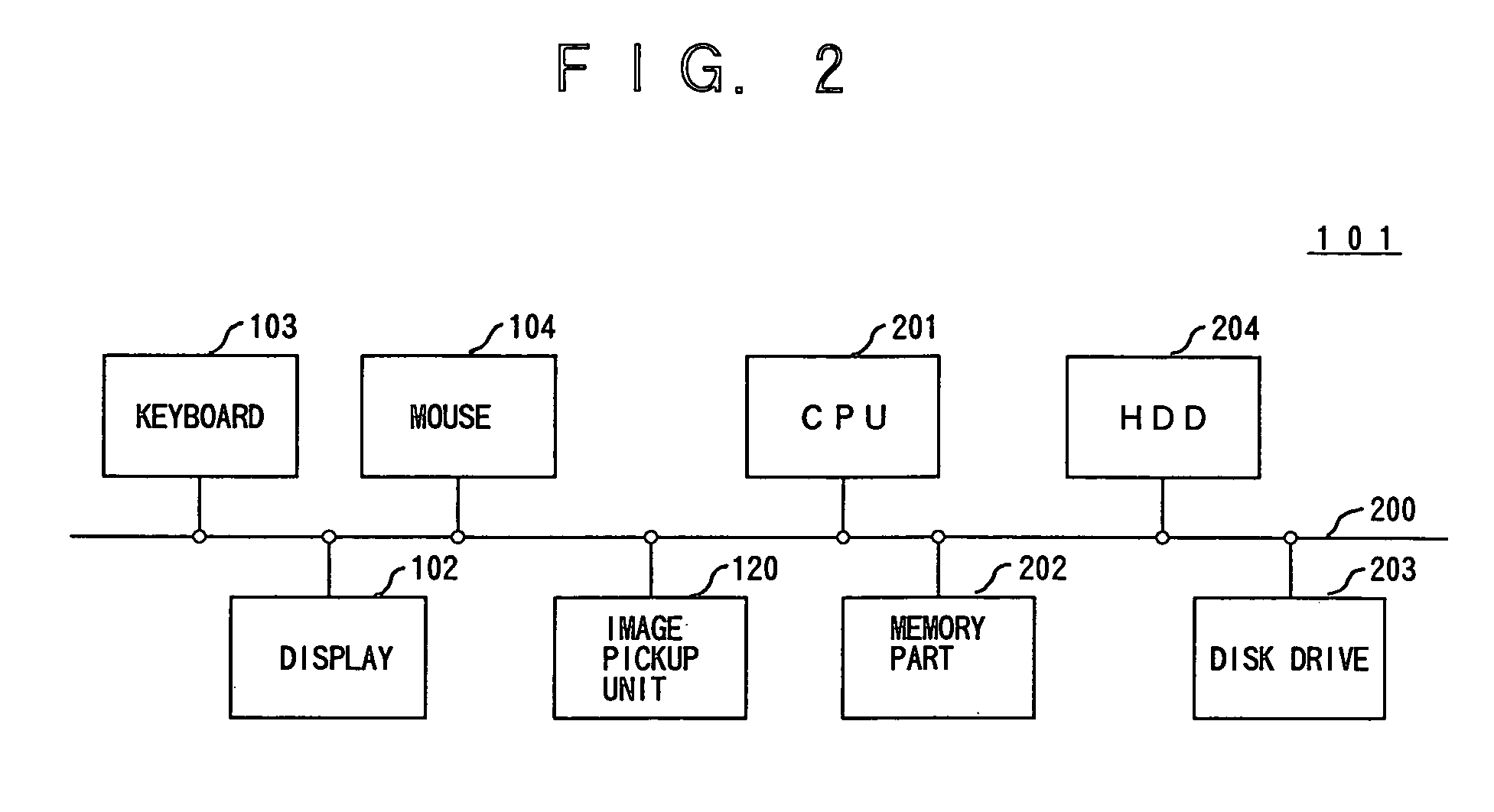
[0060]First, a description will be given of the operation when the computer system 100 forms a transmitting end apparatus. FIG. 3 is a flow chart for explaining the operation of the CPU 201 of the computer system 100 which forms the transmitting end apparatus. The process shown in FIG. 3 corresponds to a program which is stored in the computer-readable storage medium according to the present invention.

[0061]In FIG. 3, a step 31 decides whether or not a mailer which generates a multi-media signature file at the transmitting end is started. When the decision result in the step 31 becomes YES, a step 32 creates a mail text or body of an electronic mail by a procedure similar to a known procedure used to create a text-based electronic mail. A signature file generally refers to a file which includes personal information of the user. On the other hand, a multi-media signature file refers to a signature file which adapts to multi-media. In this embodiment, the mailer creates an electronic ...

second embodiment

[0072]Next, a description will be given of the operation when the computer system 100 forms a receiving end apparatus having a mailer which is adapted to the multi-media signature file. FIG. 5 is a flow chart for explaining the operation of the CPU 201 of the computer system 100 which forms the receiving end apparatus. The process shown in FIG. 5 corresponds to a program which is stored in the computer-readable storage medium according to the present invention.

[0073]In FIG. 5, a step 11 decides whether or not a mailer at the receiving end, which is adapted to the multi-media signature file, is started. When the decision result in the step 11 becomes YES, a step 12 receives an electronic mail from a transmitting end apparatus via a communication network such as the Internet and a known mail server (not shown). In this embodiment, it is assumed for the sake of convenience that the received electronic mail has been created by the process described above in conjunction with FIG. 3. Furt...

third embodiment

[0084]Next, a description will be given of the operation when the computer system 100 forms a receiving end apparatus having a mailer which is not adapted to the multi-media signature file. FIG. 11 is a flow chart for explaining the operation of the CPU 201 of the computer system 100 which forms the receiving end apparatus. The process shown in FIG. 11 corresponds to a program which is stored in the computer-readable storage medium according to the present invention.

[0085]In FIG. 11, a step 51 decides whether or not the mailer at the receiving end, which is not adapted to the multi-media signature file, is started. When the decision result in the step 51 becomes YES, a step 52 receives an electronic mail from a transmitting end apparatus via a communication network such as the Internet and a known mail server (not shown). A step 53 displays a list of the received electronic mail on the display 102. A step 54 includes the multi-media signature file within the mil text of the electron...


PUM


Abstract

An electronic apparatus, a control apparatus, and a storage medium include a transmitter transmitting electronic mail in which a symbol including image information, which enables a sender to be specified therefrom, is included within an electronic signature file of the electronic mail, said electronic signature file including an email address of the sender. The transmitter transmits the electronic mail only when an error, between the image information and prestored image information, is within a predetermined range.

Description

BACKGROUND OF THE INVENTION[0001]This application claims the benefit of a Japanese Patent Application No. 11-304627 filed Oct. 26, 1999, in the Japanese Patent Office, the disclosure of which is hereby incorporated by reference.[0002]1. Field of the Invention[0003]The present invention generally relates to electronic apparatuses, control apparatuses and storage media, and more particularly to an electronic apparatus having an electronic mail function, a control apparatus for controlling such an electronic apparatus, and a computer-readable storage medium which stores a program for causing a computer to have the electronic mail function.[0004]In this specification, an electronic apparatus refers to an apparatus having an electronic mail function, and includes computers such as personal computers, word processors, electronic notebooks, and intelligent telephone sets which includes various functions in addition to the normal telephone functions. In addition, the electronic mail functio...

Claims


Application Information

Patent Timeline
IPC IPC(8): G06F15/16G06F15/173G06F17/00H04K1/00H04L9/00G06F13/00G06Q10/00H04L9/32H04L12/58H04L29/06
CPCG06Q10/107G06Q20/3674G06Q20/382H04L51/00H04L63/123H04L9/3247H04L63/12H04L51/26Y10S707/99948H04L2209/60Y10S707/99945H04L51/226H04L51/10
Inventor YOSHIZAWA, HIROYUKI
Owner FUJITSU LTD
Learn More