
Enhanced interleave type error correction method and apparatus

a technology of error correction and interleave, applied in the field of digital communication systems, can solve problems such as noise and distortion, noise and distortion, and distortion at the output, and achieve the effects of improving accuracy, improving accuracy, and improving accuracy

Inactive Publication Date: 2005-12-27
SEAGATE TECH HDD HLDG +3
View PDF8 Cites 17 Cited by
  • Summary
  • Abstract
  • Description
  • Claims
  • Application Information

AI Technical Summary

Problems solved by technology

All channels occasionally introduce noise and distortion into the signals they carry.
The noise and the distortion change the transmitted signal and thus can create errors at the output.
Then, the user data and the parity check symbols, together known as codewords, are all transmitted or stored through the channel and may be corrupted by noises and distortions.
Because of the noises and distortions in the channel, the detector occasionally makes incorrect estimations.
Consequently, the input to the decoder has errors.
Sometimes the detector is not able to make a clear estimation from its input.
Sometimes the decoder can not find a valid codeword, subject to the encoding rule, because of excessive errors or erasures in its input.
In this case, the decoder may declare a failure in decoding.
However, the encoder and decoder for such codes are usually too complicated to implement because the code required is too long.
The burst errors usually affect two or more consecutive bits and, because of the interleaving, corrupt two or more codewords.
If a single block suffers from one very long burst error or more than one burst, the ECC decoder may not be able to correct the corrupted data because more than the maximum number of symbols of ECC encoded data will be corrupted in a single ECC codeword.
When the interleaved block is decoded, if the decoder fails to decode any one of the codewords, the attempt to decode the whole block is considered a failure.
There are some major weaknesses of this prior art.
First, hardware ECC decoders are very sophisticated circuits, so dual decoders at the destination incurs extra complexity in hardware and development, especially for high data rate applications.
Thus, the requirement of using two different decoders to decode an interleaved codeword is not desirable.
This prior art cannot be applied because it requires a change in the encoding scheme.

Method used


Image

  • Enhanced interleave type error correction method and apparatus
  • Enhanced interleave type error correction method and apparatus
  • Enhanced interleave type error correction method and apparatus

Examples


Embodiment Construction

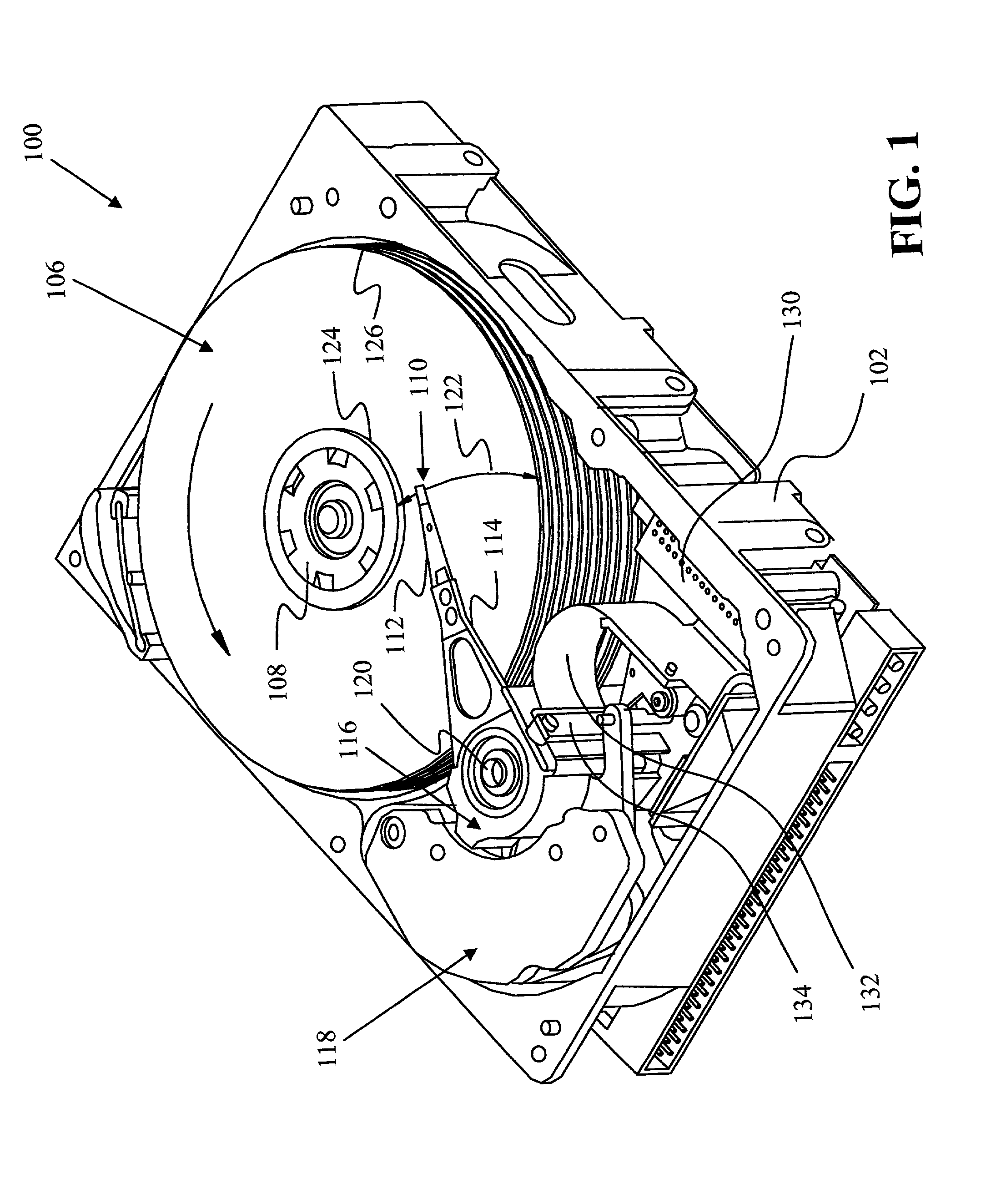
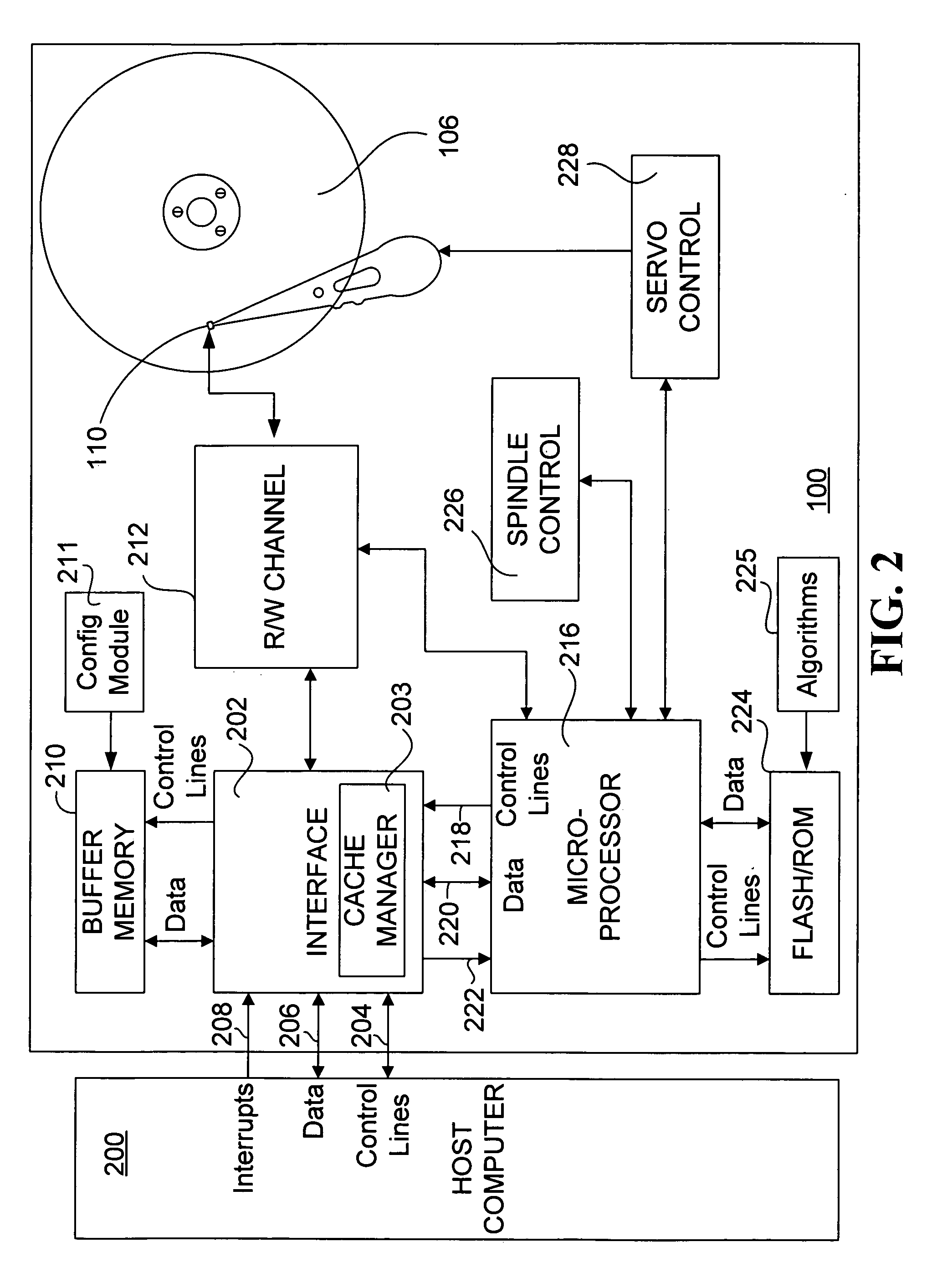
[0027]A disc drive 100 constructed in accordance with a preferred embodiment of the present invention is shown in FIG. 1. The disc drive 100 includes a housing with a base 102 to which various components of the disc drive 100 are mounted. A top cover (not shown) cooperates with the base 102 to form an internal, sealed environment for the disc drive in a conventional manner. The components include one or more discs 106 which are mounted on a spindle motor (not shown) by a disc clamp 108. Information is written to and read from tracks on the discs 106 through the use of an actuator assembly 116. The actuator assembly 116 includes a plurality of actuator arms 114 which extend towards the discs 106, with one or more flexures 116 extending from each of the actuator arms 114. Mounted at the distal end of each of the flexures 116 is a head 118 which includes an air bearing slider 110 enabling the head 110 to fly in close proximity above the corresponding surface of the associated disc 106....


PUM

PropertyMeasurementUnit
transmission indexaaaaaaaaaa
thresholdaaaaaaaaaa
Hamming distanceaaaaaaaaaa

Abstract

An enhanced interleave type error correction method is provided in which decoding of an enhanced interleave block is done. Subsequently the decoding may be done by decoding the estimated codewords multiple times using a single error correction code. In addition, a decoder and a digital communication system for implementing the enhanced interleave type error correction method are provided.

Description

CROSS REFERENCE TO RELATED APPLICATIONS[0001]This application claims the benefit of U.S. Provisional Application No. 60 / 263,625, filed Jan. 23, 2001.FIELD OF THE INVENTION[0002]The present invention relates generally to digital communication systems. More particularly, the present invention relates to digital communication systems that use interleaved error correction code to protect data as it passes through a noisy communication channel.BACKGROUND OF THE INVENTION[0003]Digital communication systems are designed to transmit user data in some digitized form from a source to a destination The means coupling the source and destination can be a simple conducting wire, a global satellite system or a data storage system, such as a magnetic disk drive or an optical compact disk. The coupling means is often generalized as a channel between the source and destination.[0004]All channels occasionally introduce noise and distortion into the signals they carry. The noise and the distortion chan...

Claims


Application Information

Patent Timeline
Patent Type & Authority Patents(United States)
IPC IPC(8): G11B20/10G11B20/18H03M13/27
CPCG11B20/1866H03M13/27G11B20/10009
Inventor LIU, BINSENG, EDMUN CHIANSONGKAN, UTTHENG
Owner SEAGATE TECH HDD HLDG
Learn More