
Method and apparatus for grinding cam with re-entrant surface

a technology of re-entrant surface and grinding cam, which is applied in the direction of edge grinding machines, grinding machine components, manufacturing tools, etc., can solve the problems of cam profile error, long grinding time, and interferen

Active Publication Date: 2005-12-27
TOYODA MASCH WORKS LTD
View PDF6 Cites 8 Cited by
  • Summary
  • Abstract
  • Description
  • Claims
  • Application Information

AI Technical Summary

Benefits of technology

[0008]Accordingly, it is a primary object of the present invention to provide an improved method and apparatus capable of grinding a cam having a re-entrant surface with a small-diameter grinding wheel precisely and efficiently.
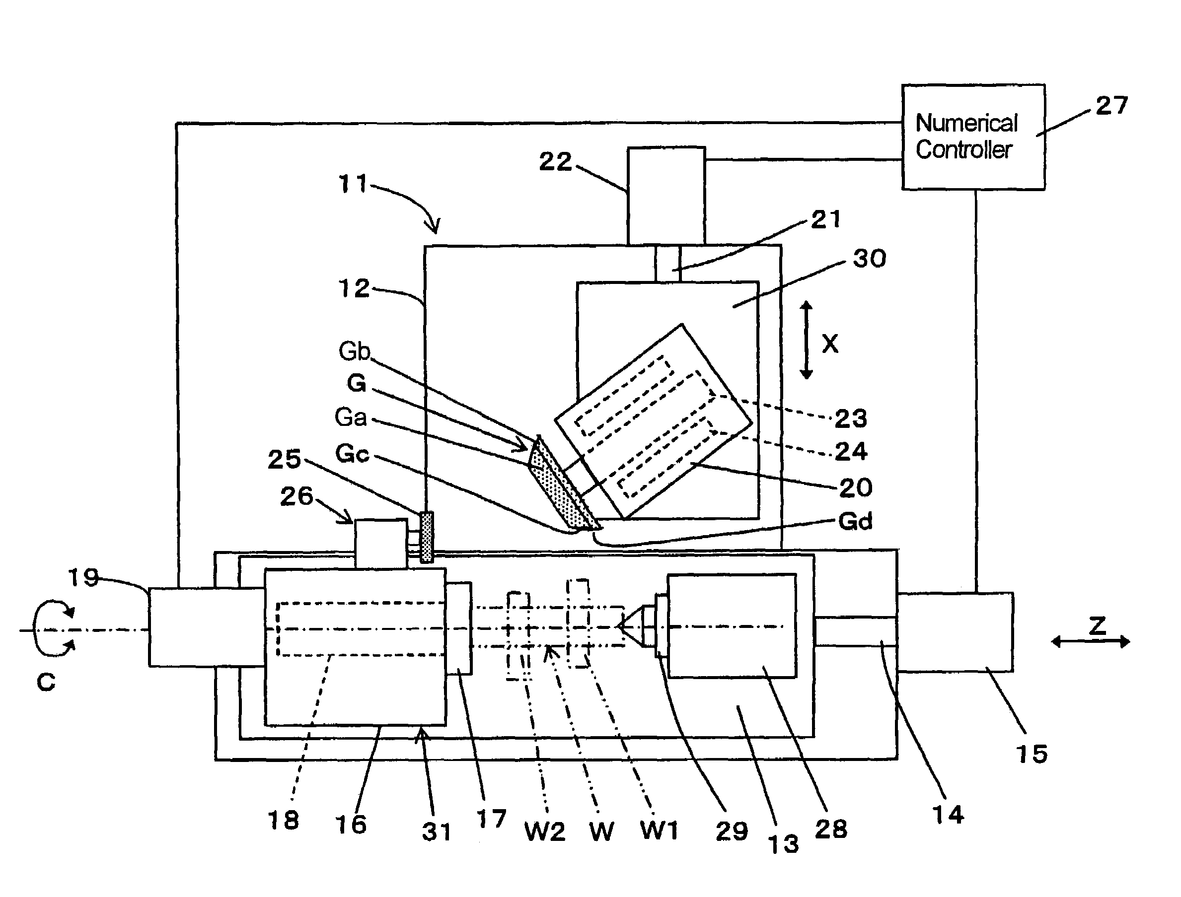
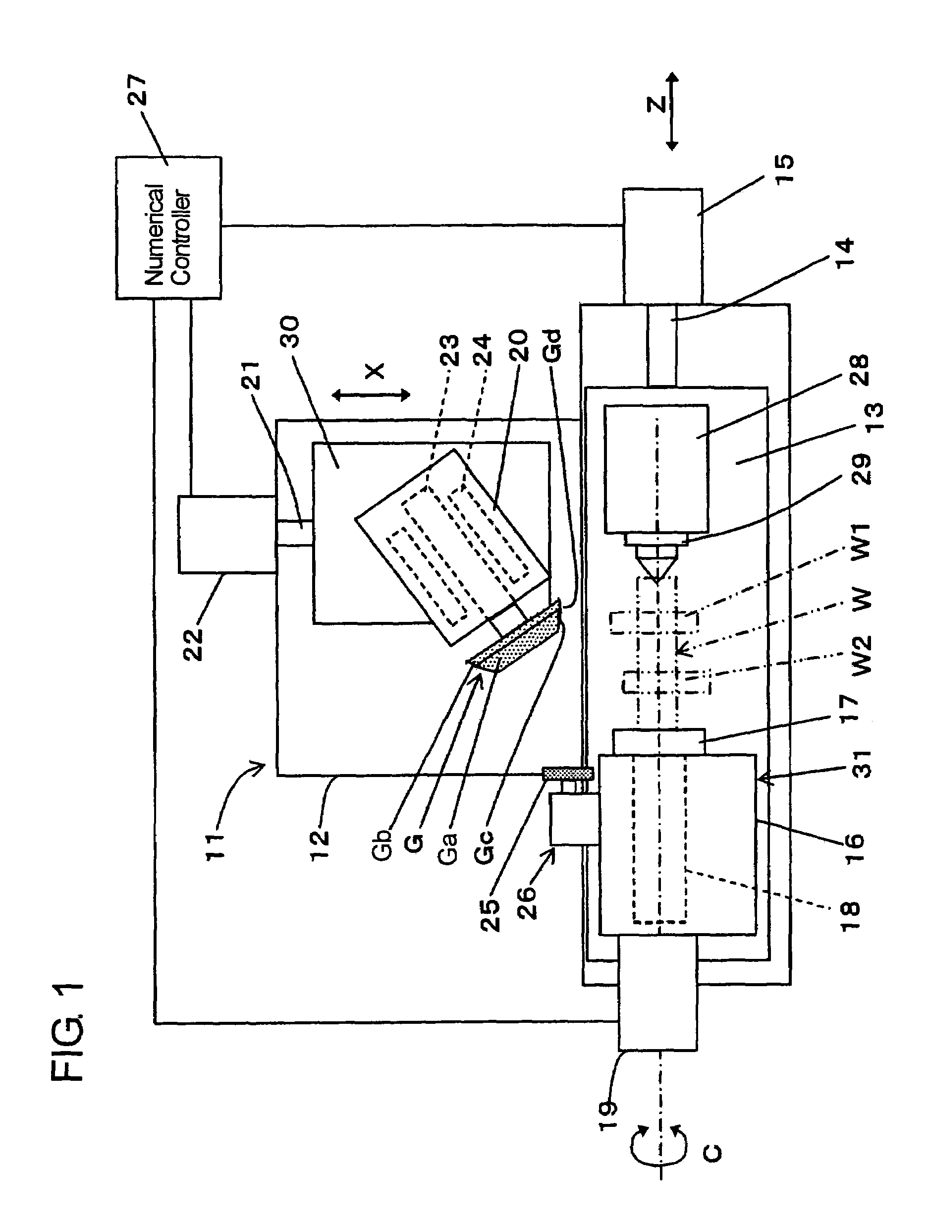
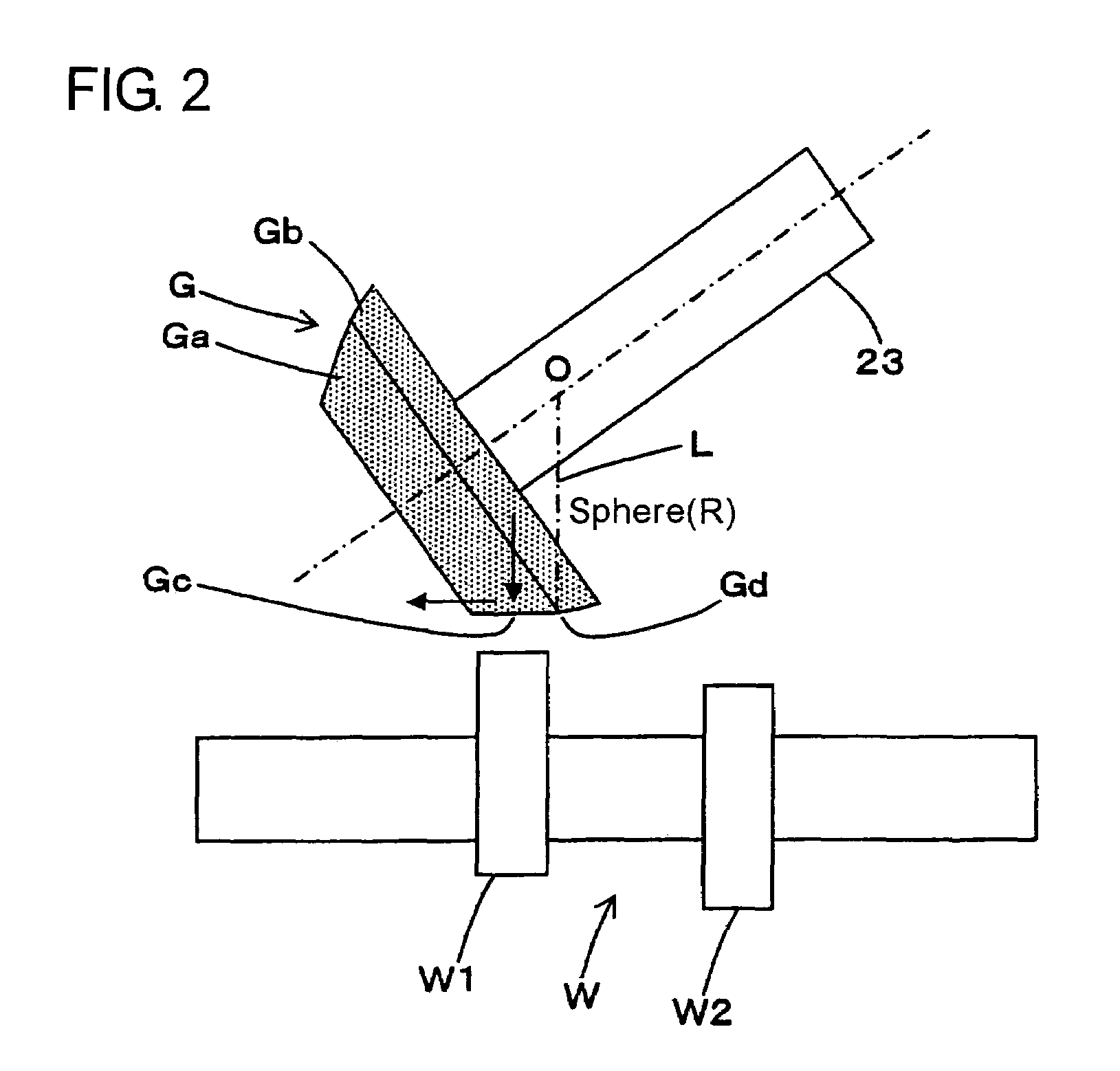
[0011]In the method and apparatus as constructed above, the workpiece and the grinding wheel are relatively moved in the Z and X-axis directions perpendicular to each other, the rotational axis of the grinding wheel is inclined relative to the X-axis, and the grinding wheel is composed of the taper section having the generating line parallel to the Z-axis and the spherical section connecting with the generating line at the maximum diameter portion of the taper section. While performing the cam profile generating motion, the grinding wheel is controlled to perform the plunge grinding feed toward the workpiece in the X-axis direction to effect the plunge grinding on the cam of the workpiece and then, while performing the cam profile generating motion, is controlled to perform the traverse grinding feed in the Z-axis direction to effect the traverse grinding on the cam. Thus, the cam of the workpiece can be efficiently ground with the taper section of the grinding wheel in the plunge grinding, and then, the cam can be ground with the spherical section of the grinding wheel in the traverse grinding without involving an error in cam profile due to the difference in the grinding wheel diameter. Accordingly, it can be realized to grind the cam efficiently and precisely.

Problems solved by technology

However, an interference takes place between the wheel head and the workpiece support device where the diameter of the grinding wheel is made to be small in the structure that the rotational axes for the workpiece and the grinding wheel are kept in parallel.
For this reason, where the grinding wheel has its diameter which differs from that set in preparing the cam profile generating NC data, an error occurs on the cam profile of the cam which is ground with the grinding wheel.
However, where the attempt is made, the infeeding at the traverse feed end of the grinding wheel against the workpiece in the X-axis direction and the traverse grinding feeding have to be repeated many times, thereby resulting in a long grinding time.

Method used


Image

  • Method and apparatus for grinding cam with re-entrant surface
  • Method and apparatus for grinding cam with re-entrant surface
  • Method and apparatus for grinding cam with re-entrant surface

Examples


Embodiment Construction

[0018]Hereafter, a method and apparatus for grinding a cam having a re-entrant surface in one embodiment according to the present invention will be described with reference to the accompanying drawings. Referring now to FIG. 1, a numerical control cam grinding machine 11 has a table 13 slidably mounted on a bed 12 thereof, and the table 13 is moved by a servomotor 15 through a ball screw 14 in a Z-axis direction. A work head 16 is fixed on the table 13, and a work spindle 18 for grasping one end of a workpiece W by a chuck 17 is rotatably carried on the work head 16 and is drivingly rotated by a servomotor 19 to rotate the workpiece W about a C-axis extending in parallel to the Z-axis. A foot stock 28 facing the work head 16 is fixed on the table 13 to be adjustable in position. The foot stock 28 fits therein a ram 29 to be slidable on the axis of the work spindle 18, and a center (not numbered) fixedly inserted into one end of the ram 29 is fit in a center hole formed at the other ...


PUM

PropertyMeasurementUnit
diameteraaaaaaaaaa
widthaaaaaaaaaa
inclination angleaaaaaaaaaa

Abstract

A workpiece W and a grinding wheel G are relatively moved in Z and X-axis directions perpendicular to each other, the rotational axis of the grinding wheel is inclined relative to the X-axis, and the grinding wheel is composed of a taper section Ga having a generating line parallel to the Z-axis and a spherical section Gb connecting with the generating line at the maximum diameter portion of the taper section Ga. While performing a cam profile generating motion, the grinding wheel is controlled to perform a plunge grinding feed toward the workpiece in the X-axis direction to effect a plunge grinding on the cam of the workpiece and then, while performing the cam profile generating motion, is controlled to perform a traverse grinding feed in the Z-axis direction to effect a traverse grinding on the cam.

Description

[0001]This application is based on and claims priority under 35 U.S.C. 119 with respect to Japanese Application No. 2004-220701 filed on Jul. 28, 2004.BACKGROUND OF THE INVENTION[0002]1. Field of the Invention[0003]The present invention relates to a method and apparatus for grinding cams having a re-entrant surface with a grinding wheel.[0004]2. Discussion of the Related Art[0005]Heretofore, there has been known a method of grinding cams on a workpiece while the rotation about a C-axis of the workpiece carried on a workpiece support device and the feed in an X-axis direction of a wheel head carrying a grinding wheel are controlled by a numerical controller in a simultaneous two-axis control mode. In recent years, requirements in cam shape have become complicated and highly precise with the increase in performance of engines, and there is an increasing demand for cams with a re-entrant surface (A) as shown in FIG. 4. A small diameter grinding wheel which is able to contact with the r...

Claims


Application Information

Patent Timeline
Patent Type & Authority Patents(United States)
IPC IPC(8): B24B1/00B24B19/12
CPCB24B1/00B24B19/12
Inventor IDO, MASAHIRO
Owner TOYODA MASCH WORKS LTD
Learn More