Semiconductor device and manufacturing method therefor
a semiconductor and manufacturing method technology, applied in the direction of organic semiconductor devices, instruments, optics, etc., can solve the problems of polysilicon films, polysilicon films, and the entire row of pixels being completely off, so as to increase the reliability of tft, reduce the effect of deterioration due to hot carrier and effective suppression of deterioration
- Summary
- Abstract
- Description
- Claims
- Application Information
AI Technical Summary
Benefits of technology
Problems solved by technology
Method used
Image
Examples
embodiment 1
[Embodiment 1]
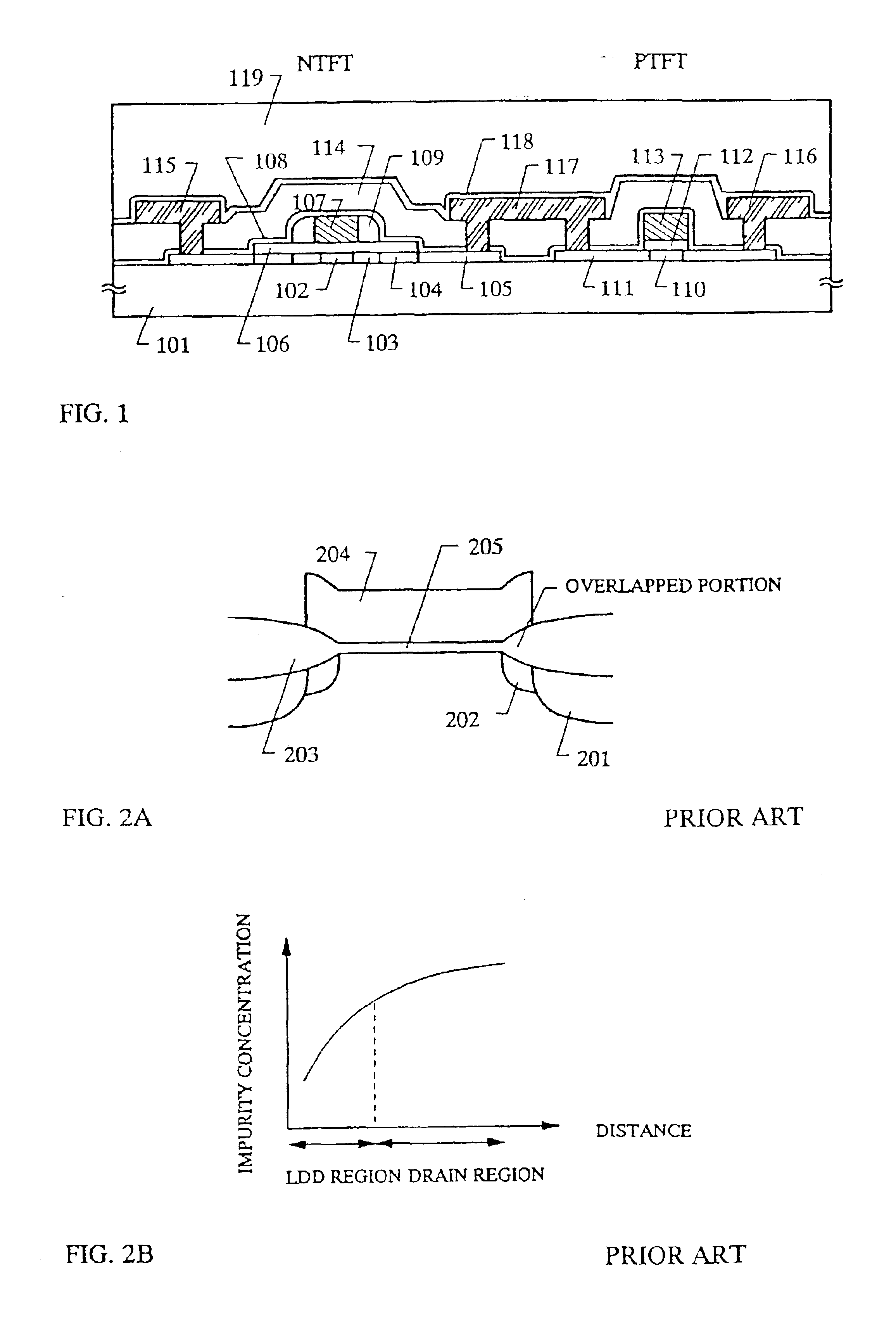
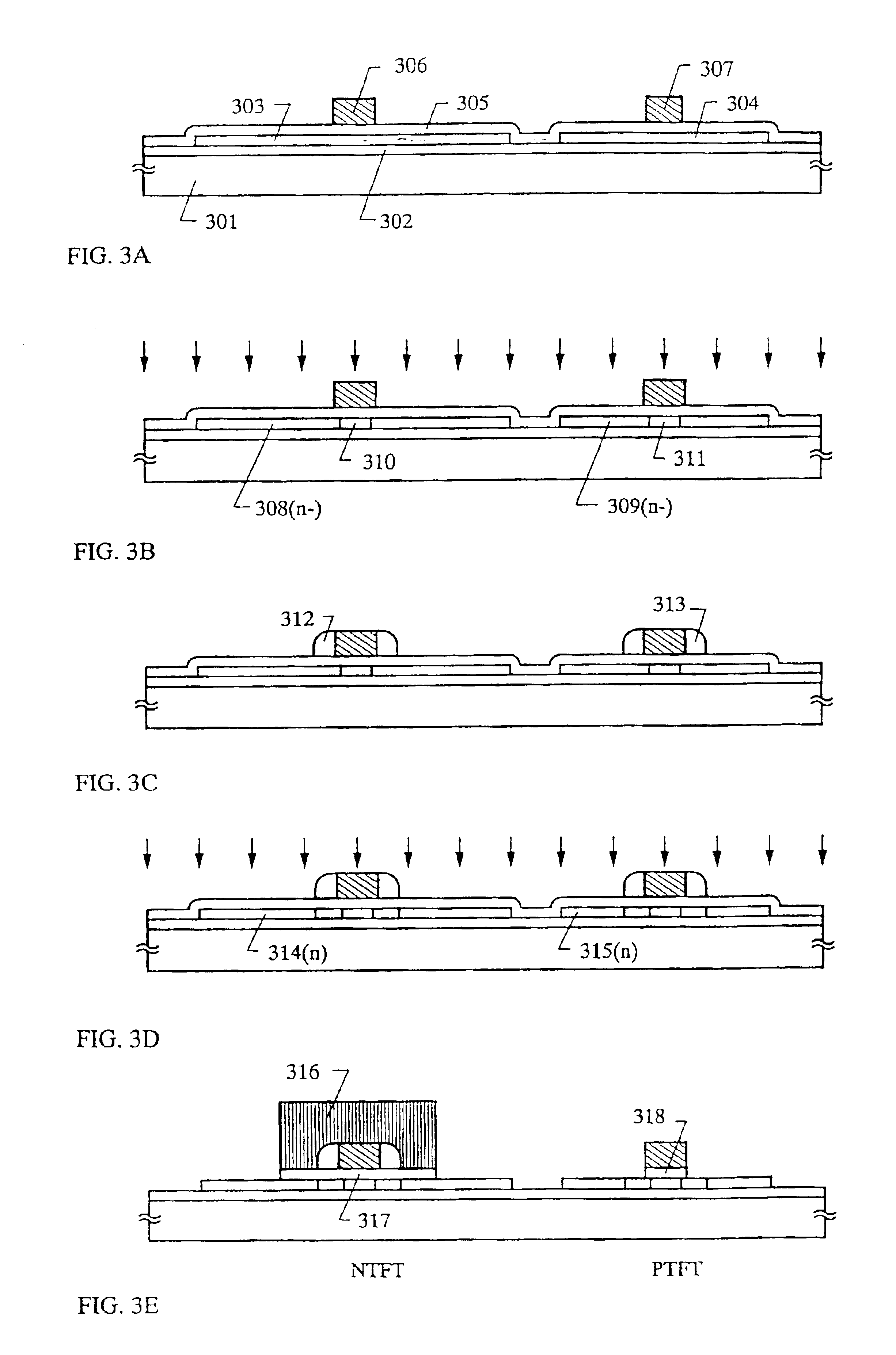
[0104]In embodiment 1, the manufacturing method of the CMOS circuit shown in FIG. 1 is explained using FIGS. 3A to 3E, FIGS. 4A to 4D, and FIGS. 5A-5B.
[0105]First, a 200 nm silicon oxide film 302 that becomes a base film is formed on a glass substrate 301. It may laminate a silicon nitride film onto the base film, and may use only a silicon nitride film. Plasma CVD, thermal CVD, or sputtering may be used as a film deposition method. Of course, doping boron into the silicon nitride film is effective to increase the radiation effect.
[0106]Next, a 50 nm amorphous silicon film is formed by plasma CVD, thermal CVD, or sputtering, on the silicon oxide film 302. Crystallization of the amorphous silicon film is carried out afterward by using the technique disclosed in Japanese Patent Application Laid-open No. Hei 7-130652, forming a semiconductor film containing crystals. This process is explained using FIGS. 5A and 5B.
[0107]First, a silicon oxide film 502 is formed as a base ...
embodiment 2
[Embodiment 2]
[0146]Undoped Si (an intrinsic silicon layer or an undoped silicon layer), in which impurities are intentionally not doped, is used in embodiment 1 for the sidewalls. However, in embodiment 2, a phosphorous doped silicon layer (“n+”-Si layer), in which phosphorous is doped during film formation, or a boron doped silicon layer (“p+”-Si layer) is used. It is needless to say that the silicon layer may be amorphous, non-crystalline, or micro-crystalline.
[0147]By using a silicon layer doped with phosphorous or boron, the entire sidewall portion is made low resistance, and the possible change in characteristics originating in fluctuation of the phosphorous concentration profile can be eliminated, which is the fear of process shown in FIG. 3D.
embodiment 3
[Embodiment 3]
[0148]Undoped Si (an intrinsic silicon layer or an undoped silicon layer), in which impurities are intentionally not doped, is used in embodiment 1 for the sidewalls. However, in embodiment 3, a silicon layer that contains either of carbon (C), nitrogen (N), or oxygen (O) is used, to thereby increase the resistive component of the sidewalls. Of course, the silicon layer may be either amorphous, crystalline, or micro-crystalline. Further, oxygen is best as the impurity to be used.
[0149]Namely, it may only dope with carbon, nitrogen, or oxygen at 1 to 50 atomic % (typically, from 10 to 30 atomic %) when forming the silicon layer that becomes the sidewalls. Oxygen at 20 atomic % is doped in this embodiment 3.
[0150]With employing the structure of embodiment 3, the resistive component due to the sidewalls becomes larger. Accordingly, it may take such a structure that the capacitive component in which the sidewalls act as the dielectric in response to the applied gate voltag...
PUM
| Property | Measurement | Unit |
|---|---|---|
| length | aaaaa | aaaaa |
| length | aaaaa | aaaaa |
| length | aaaaa | aaaaa |
Abstract
Description
Claims
Application Information
 - R&D
- Intellectual Property
- Life Sciences
- Materials
- Tech Scout
- Unparalleled Data Quality
- Higher Quality Content
- 60% Fewer Hallucinations
Browse by: Latest US Patents, China's latest patents, Technical Efficacy Thesaurus, Application Domain, Technology Topic, Popular Technical Reports.
© 2025 PatSnap. All rights reserved.Legal|Privacy policy|Modern Slavery Act Transparency Statement|Sitemap|About US| Contact US: help@patsnap.com


