Spread spectrum clock generation circuit, jitter generation circuit and semiconductor device
a clock generation circuit and jitter generation technology, applied in the direction of instruments, code conversion, modulation, etc., can solve the problems of increased electromagnetic wave radiation at this part, increased cost, and inability to secure normal operation, so as to reduce radiation noise and reduce the effect of operation speed and radiation nois
- Summary
- Abstract
- Description
- Claims
- Application Information
AI Technical Summary
Benefits of technology
Problems solved by technology
Method used
Image
Examples
first embodiment
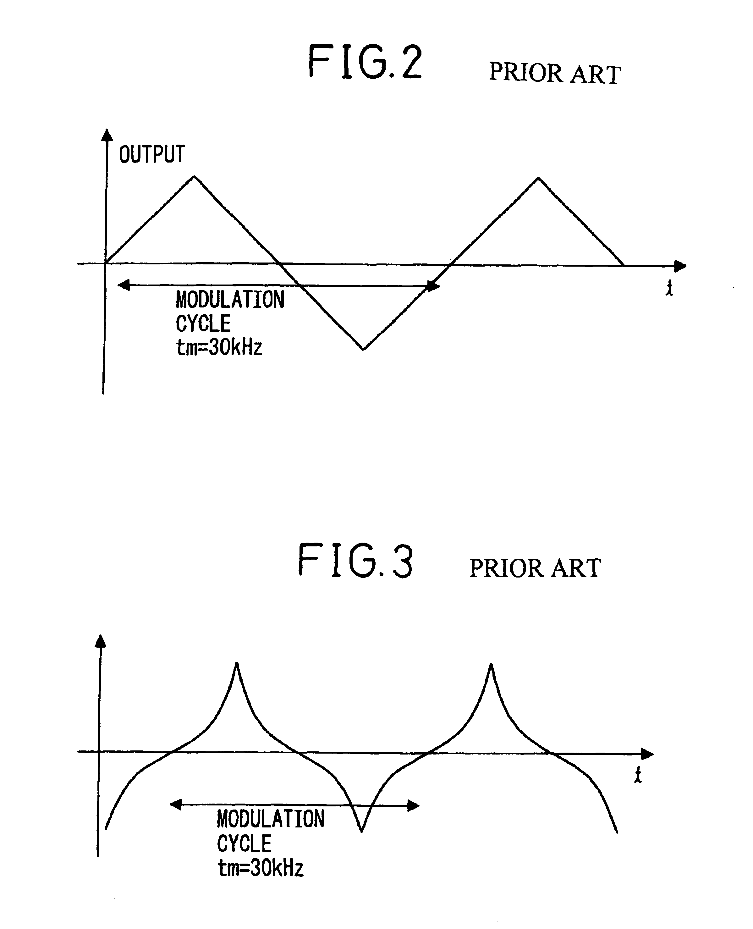
[0125]FIG. 8 is a diagram showing the configuration of the spread spectrum clock generation (SSCG) circuit in the present invention. As shown schematically, this circuit is a circuit in which a clock CK M / N times the reference clock CLK is generated therefrom by the use of a PLL circuit as in the circuit shown in FIG. 1 but differs from a conventional one in that the period of a spread spectrum modulation signal generated by a modulator 22 changes in order as shown in FIG. 5A.
[0126]As shown in FIG. 8, in the SSCG circuit in the first embodiment, a control circuit 21 generates an output code such as shown in FIG. 9 and outputs it to the modulator 22. The modulator 22 is a voltage digital-to-analog converter (VDAC) and converts the output code into an analog voltage signal. In this manner, a spread spectrum modulation analog voltage signal as shown in FIG. 5A is obtained. When the voltage signal does not change smoothly because of the voltage change width corresponding to the least si...
fifth embodiment
[0148]In the SSCG circuit in the fifth embodiment, the control circuit 21 generates an output code as shown in FIG. 24 and outputs it to the modulator 22. In the first period, the value of this output code increases from the middle value to the first maximum value and decreases to the first minimum value, and then increases again. The period enters the second period when the middle value is reached, and after the value increases from the middle value to the second maximum value, it decreases to the second minimum value, and then increases again. When the middle value is reached, the period enters the first period again, and the same operation is repeated. In this example, the length of one period of the first period is different from that of the second period. If the voltage signal does not change smoothly because of the voltage change width corresponding to the least significant bit of the output code, a low-pass filter is used for smoothing. In this manner, the voltage to be appli...
second embodiment
[0154]In this manner, the spread spectrum voltage signal whose amplitude changes for each period is obtained. In the second embodiment also, both the amplitude and the period of the spread spectrum voltage signal change. In order to generate a spread spectrum voltage signal only the amplitude of which changes and the period of which does not change, a constant current source capable of charging or discharging with different currents is provided in the circuit shown in FIG. 26A and the current to be supplied is switched for each period. In this case, the switch control circuit 35 switches the power supply between charging and discharging in a predetermined period.
[0155]Further, the spread spectrum modulation signal shown in FIG. 67 can be also obtained in the above circuit. In this case, the current to be supplied is switched in each cycle.
[0156]Although a case of switching between two amplitudes is shown here, it is also possible to switch among three or more amplitudes.
[0157]As des...
PUM
 Abstract
Description
Claims
Application Information
 - R&D
- Intellectual Property
- Life Sciences
- Materials
- Tech Scout
- Unparalleled Data Quality
- Higher Quality Content
- 60% Fewer Hallucinations
Browse by: Latest US Patents, China's latest patents, Technical Efficacy Thesaurus, Application Domain, Technology Topic, Popular Technical Reports.
© 2025 PatSnap. All rights reserved.Legal|Privacy policy|Modern Slavery Act Transparency Statement|Sitemap|About US| Contact US: help@patsnap.com


