
Mid-mount mower having a mower unit disposed between front and rear wheels

a mower unit and mower technology, applied in the field of mid-mount mowers, can solve the problems of arousing a sense of uneasiness in the operator, severe control is required to raise the front of the vehicle body by a desired amount, damage to jack members or adjacent components, etc., to suppress a cost increase and a structural complication, and relieve the operator from a sense of uneasiness

Inactive Publication Date: 2005-12-13
KUBOTA LTD
View PDF9 Cites 24 Cited by
  • Summary
  • Abstract
  • Description
  • Claims
  • Application Information

AI Technical Summary

Benefits of technology

[0010]The object of this invention is to provide a mower with a function of raising a vehicle body easily while suppressing a cost increase and a structural complication, relieving the operator from a sense of uneasiness, and avoiding serious damage to the ground.
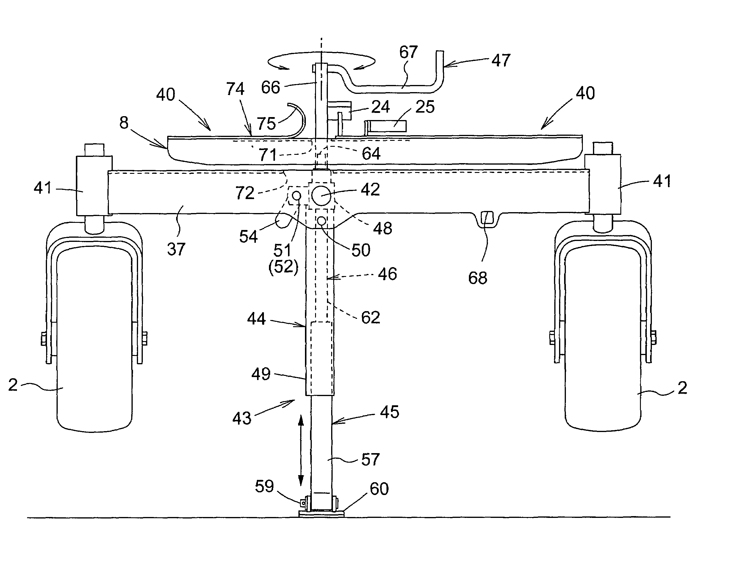
[0012]In the mower as noted above, the front of the vehicle body may be raised by switching the jack from the storage position to the operative position and extending the jack. As a result, the inside of the mower is exposed to allow a maintenance operation, such as cleaning the inside of the mower deck or changing the blades, to be carried out easily without the trouble of detaching the mower unit from the vehicle body. Since the front of the vehicle body is raised by extending the main jack body vertically erected, the vehicle body may be raised in a stable, well-balanced position with little shifting of the center of gravity of the vehicle body. Further, in such a raising operation, only a load in a jack-extending direction, i.e. vertical direction or substantially vertical direction, is applied to the ground, and the ground surface contacted by the main jack body is subject to little damage. As the main jack body does not undergo a strong bending force when raising the vehicle body, the structure thereof may be simplified. Furthermore, as the main jack body is stored in a transverse position extending along a transverse front frame, the main jack body is not obstructive to a running or grass cutting operation.
[0013]In a preferred embodiment of this invention, the controlled portion is upwardly exposed when the main jack body is in the vertical position relative to the ground, and a control device is provided for engaging the upwardly exposed controlled portion of the main jack body. A brake pedal is disposed in a forward portion of the body frame to be movable between a braking position and a non-braking position, and a lock device is provided for holding the brake pedal in the braking position. The brake pedal in the non-braking position blocks operation of the control device engaged with the controlled portion of the main jack body in the vertical position relative to the ground. With this construction, only when the brake pedal is held in the braking position by the lock device to produce what is called a parking state, the jack control device may be turned to raise the front of the running vehicle. This prevents an inadvertent movement of the vehicle body caused by neglecting to put on the brakes, when the front part of the vehicle body is raised by the jack.
[0017]That is, when braking the vehicle, parking the vehicle or starting the vehicle again, the operator does not need to change his or her grips on levers, as required with a construction in which levers are used to brake or park the vehicle body. It is therefore easy to make a quick response to a need for an emergency braking operation. Further, the operator may bring the vehicle body into a parking state or running state quickly by a series of operations without changing his or her grips on the levers. This eliminates the possibility of a wrong operation caused by an inadvertent contact or knock made by the operator when changing the grips on the levers.
[0018]Further, where the brake pedal and the lock pedal are arranged close to each other and side by side, the connecting structure for permitting the lock pedal to hold the brake pedal may be simplified. Since the lock pedal is operated by a foot, its juxtaposition with the brake pedal at the operator's feet does not impair operability.

Problems solved by technology

Such an operation often arouses a sense of uneasiness in the operator.
Thus, a severe control is required to raise the front of the vehicle body by a desired amount.
When the operator fails to stop the vehicle in an appropriate position, the jack member or adjacent components may be damaged due to overloading.
This will lead to a cost increase or a complicated structure.
Further, the toothed portion thrusting into the ground and acting as a pivot for the jack member in time of raising the vehicle body may badly injure the ground surface, which in many cases is turf.
As a result, the vehicle body could become unstable when raised, and the mower should be parked on as level a surface as possible.
For this purpose, it may be necessary to use an expensive material or provide a reinforcing member, which will lead to a cost increase or a complicated structure.

Method used


Image

  • Mid-mount mower having a mower unit disposed between front and rear wheels
  • Mid-mount mower having a mower unit disposed between front and rear wheels
  • Mid-mount mower having a mower unit disposed between front and rear wheels

Examples


Embodiment Construction

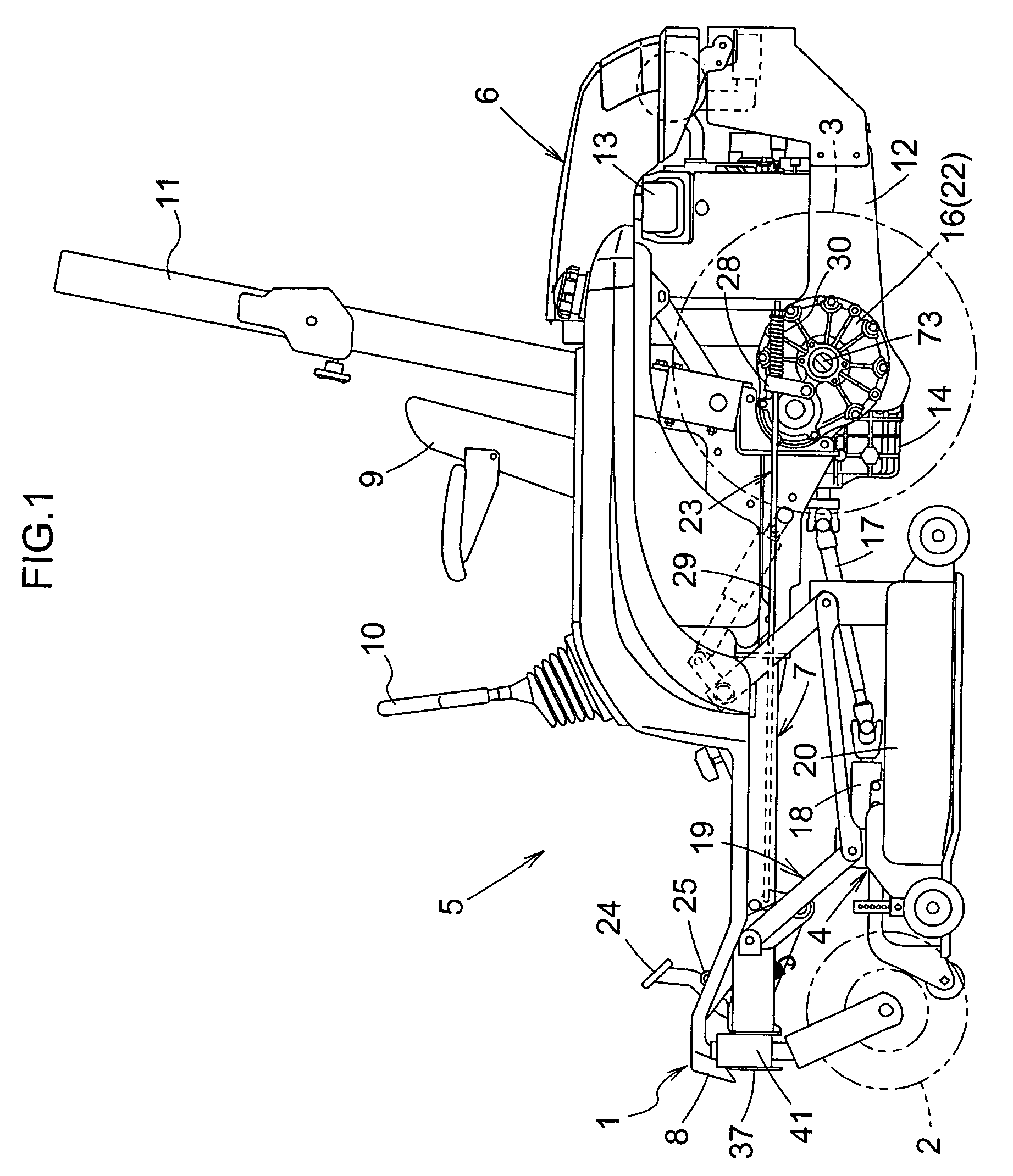
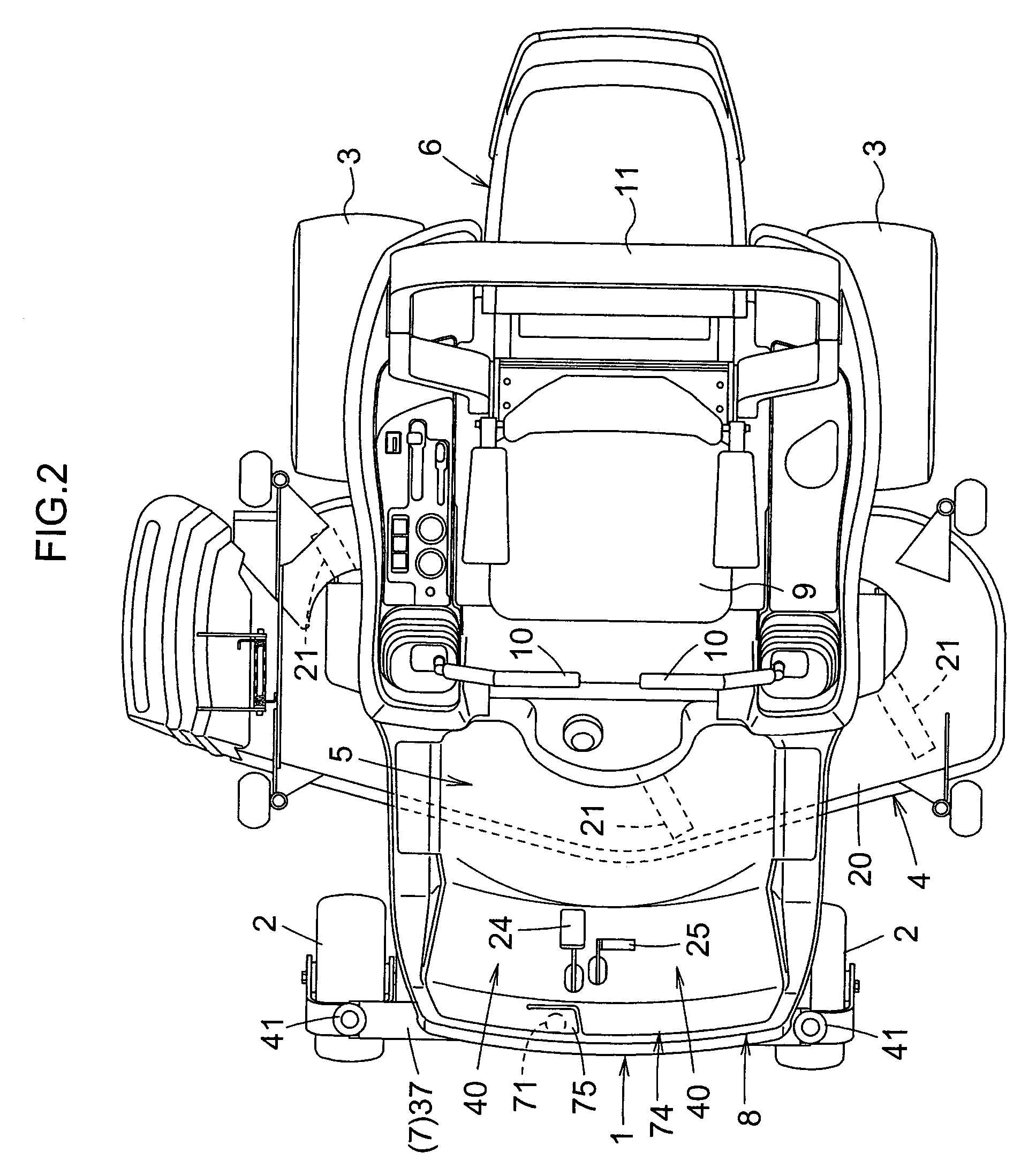
[0032]FIG. 1 shows a side elevation of a riding mid-mount mower. FIG. 2 shows a plan view of the mower. The mower includes a vehicle body 1 having a pair of right and left caster-type front wheels 2 arranged in front positions thereof to be swivelable about vertical axes. and a pair of right and left rear wheels 3 arranged in rear positions to act as drive wheels. This mower is constructed as the mid-mount type with a vertically movable mower unit 4 mounted between the front wheels 2 and rear wheels 3.

[0033]As shown in FIGS. 1 through 3, the vehicle body 1 has a driving platform 5 disposed in a forward portion thereof, and a motor section 6 disposed in a rearward portion. The driving platform 5 includes a boarding step 8 disposed on a front part of a body frame 7, an operator's seat 9 disposed in a rear part of the body frame 7, shift levers 10 pivotably arranged at right and left sides of the operator's seat 9, a rollover protective frame 11 erected on the body frame 7 rearwardly o...


PUM


Abstract

A mid-mount mower having a body frame supported above the ground by front wheels and rear wheels, the body frame having a front cross frame in a forward portion thereof with respect to a longitudinal direction of a vehicle body, and a mower unit disposed between the front wheels and rear wheels. A main jack body is mounted on the front cross frame to be pivotable about a pivot shaft extending longitudinally of the vehicle body. The main jack body is in a storage position extending along the front cross frame when pivoted to a first pivot position about the pivot shaft, and in a substantially vertical position relative to the ground when pivoted to a second pivot position about the pivot shaft. The main jack body has a controlled portion exposed upward when the main jack body is in the vertical position. The main jack body is extendible and contractible, in the vertical position relative to the ground, to raise and lower the front cross frame when an operating force is applied through a control device engaged with the controlled portion of the main jack body.

Description

BACKGROUND OF THE INVENTION[0001]1. Field of the Invention[0002]This invention relates to a mid-mount mower having a mower unit disposed between front wheels and rear wheels. More particularly, the invention relates to a mid-mount mower having a function for jacking up a front portion of a vehicle body to expose a blade-equipped plane of a mower unit.[0003]2. Description of the Related Art[0004]In a conventional mid-mount mower noted above, it is necessary to raise the front portion of the vehicle body and expose the inside of the mower unit for inspection and maintenance of interior parts of the mower unit kept mounted on the vehicle body. For this purpose, the mid-mount mower known from U.S. patent application published under No. 2002 / 0157369 has a jack member pivotably switchable between a storage position retracted toward the vehicle body and an operative position extended forwardly and downwardly of the vehicle body. When switched to the operative position, the jack member is v...

Claims


Application Information

Patent Timeline
IPC IPC(8): A01D34/64B60S9/08
CPCA01D34/64A01D2034/645A01D34/662
Inventor SAMEJIMA, KAZUOTOGOSHI, YOSHIKAZUFUJIWARA, OSAMIESAKI, YOSHIYUKIMINOURA, AKIRA
Owner KUBOTA LTD
Learn More