Rolling Bearing

a bearing and rolling bearing technology, applied in the direction of shafts and bearings, mechanical equipment, rotary machine parts, etc., can solve the problems of increasing the number of components, increasing the cost, and limiting the extent to which noise reduction is attempted, so as to suppress the cost increase and reduce the noise

Inactive Publication Date: 2017-01-26
JTEKT CORP
View PDF2 Cites 1 Cited by
  • Summary
  • Abstract
  • Description
  • Claims
  • Application Information

AI Technical Summary

Benefits of technology

The technical effect of the present invention is to provide a rolling bearing that can reduce noise while keeping the cost increase as low as possible.

Problems solved by technology

However, there is a limit to the extent to which noise is attempted to be reduced by improving the accuracy of various parts constituting the rolling bearing, and such accuracy improvement leads to cost increase.
Since the O ring is required as an additional member, increases the number of components increases, which also increases costs.

Method used


Image

  • Rolling Bearing
  • Rolling Bearing
  • Rolling Bearing

Examples


Embodiment Construction

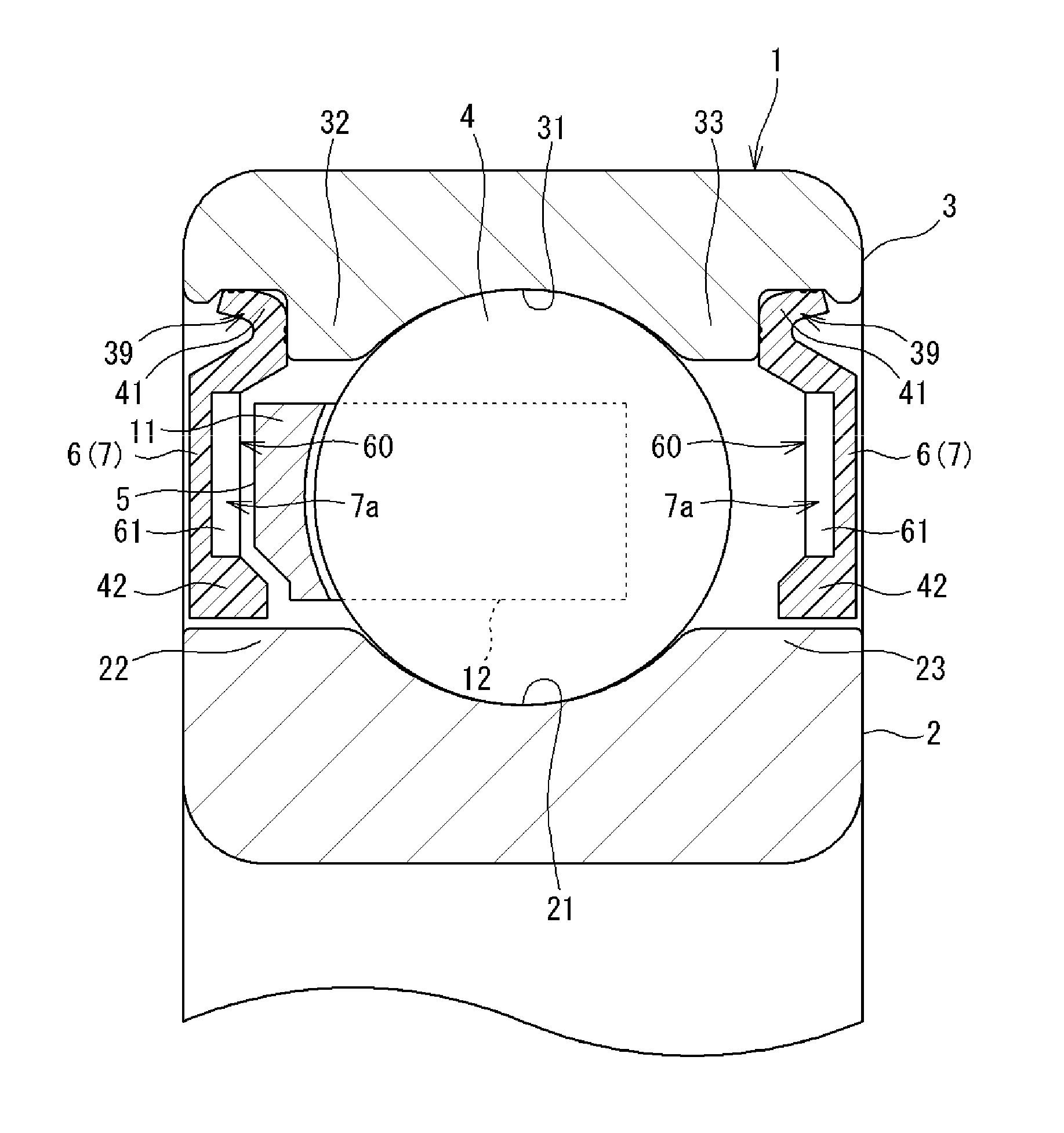
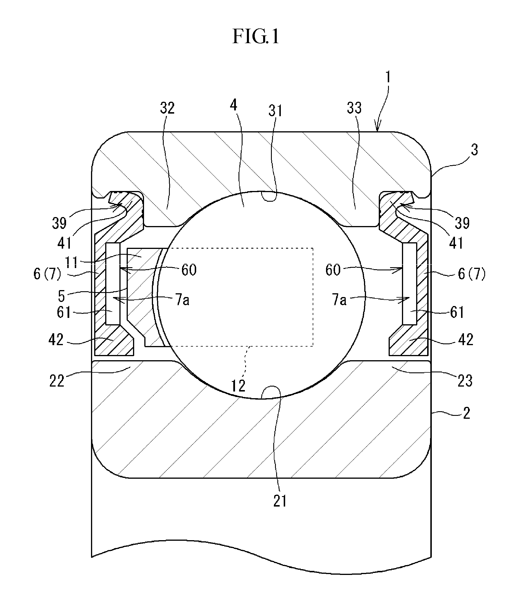
[0022]Embodiments of the present invention will now be described with reference to the drawings. FIG. 1 is a sectional view illustrating a rolling bearing according to one embodiment of the present invention. This rolling bearing 1 includes an inner ring 2, an outer ring 3, a plurality of rolling elements, an annular cage 5, and a sealing device 6. The outer ring 3 is disposed the radially outward of the inner ring 2.

[0023]The rolling elements are interposed between the inner ring 2 and the outer ring 3. The cage 5 holds the rolling elements. The rolling elements of the present embodiment are balls 4, and the rolling bearing 1 is a deep groove ball bearing.

[0024]The inner ring 2 is an annular member and, in the outer periphery thereof, an inner raceway groove 21 on which the balls 4 roll is formed. The inner ring 2 has a first shoulder portion 22 adjacent to one side of the inner raceway groove 21 in the axial direction and a second shoulder portion 23 adjacent to the other side of ...


PUM

PropertyMeasurementUnit
areaaaaaaaaaaa
elasticaaaaaaaaaa
shapeaaaaaaaaaa

Abstract

A rolling bearing includes an inner ring, an outer ring, a plurality of balls, a cage that holds the balls, and a sealing device that is attached to each of opposite sides of the outer ring in an axial direction to prevent foreign matter from entering inside the bearing. A noise-reduction portion that attenuates sound inside the bearing is formed on at least one of a surface of the cage and a bearing inner-side surface of the sealing device.

Description

INCORPORATION BY REFERENCE[0001]The disclosure of Japanese Patent Application No. 2015-144857 filed on Jul. 22, 2015 including the specification, drawings and abstract, is incorporated herein by reference in its entirety.BACKGROUND OF THE INVENTION[0002]1. Field of the Invention[0003]The present invention relates to a rolling bearing.[0004]2. Description of Related Art[0005]Rolling bearings are used for various industrial machines. A rolling bearing includes an inner ring, an outer ring, a plurality of rolling elements, and a cage. The rolling elements are interposed between the inner ring and the outer ring. The cage holds the rolling elements. When rolling bearings are used as bearings that support a motor included in a home appliance, for example, in order to suppress generation of operation noise, the rolling bearings are required to reduce noise generated due to rotation.[0006]For example, Japanese Patent Application Publication No. 2008-208976 (JP 2008-208976 A) proposes a rol...

Claims


Application Information

Patent Timeline
Patent Type & Authority Applications(United States)
IPC IPC(8): F16C33/78F16C19/06
CPCF16C19/06F16C33/7886F16C33/38F16C33/7806F16C33/7816F16C33/7843F16C33/80F16C33/7856F16C2220/04F16C2208/60F16C2208/52F16C33/7846F16C19/527
Inventor KAMAMOTO, SHIGEOMURATA, JUNJISHISHIHARA, YUKINAKAZAWA, KUNISHIGE
Owner JTEKT CORP
Why Eureka
Try Eureka