Timepiece device
a timepiece and device technology, applied in the field of timepieces, can solve the problems of affecting the thickness reduction of timepieces and the small size of timepieces, and achieve the effect of stabilizing the value of cogging torqu
- Summary
- Abstract
- Description
- Claims
- Application Information
AI Technical Summary
Benefits of technology
Problems solved by technology
Method used
Image

Examples
first embodiment
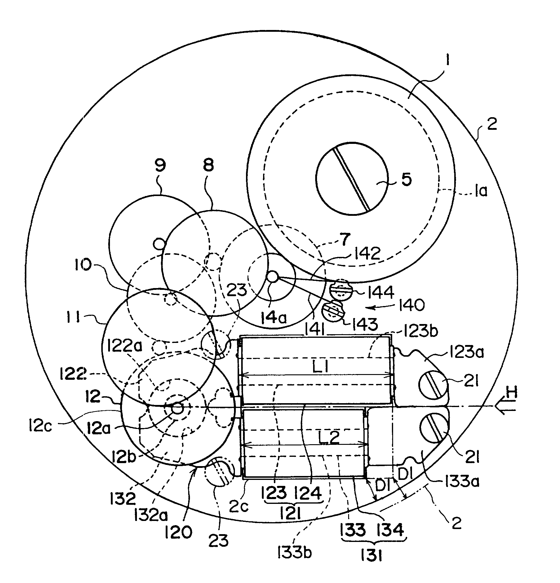
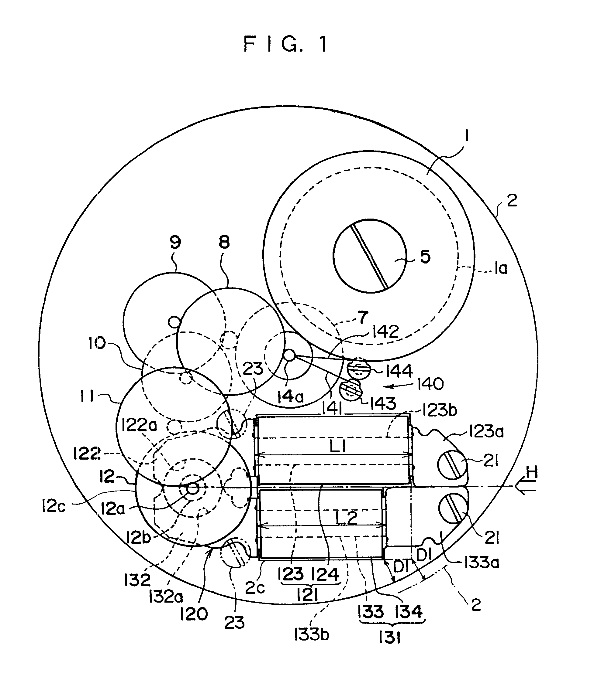
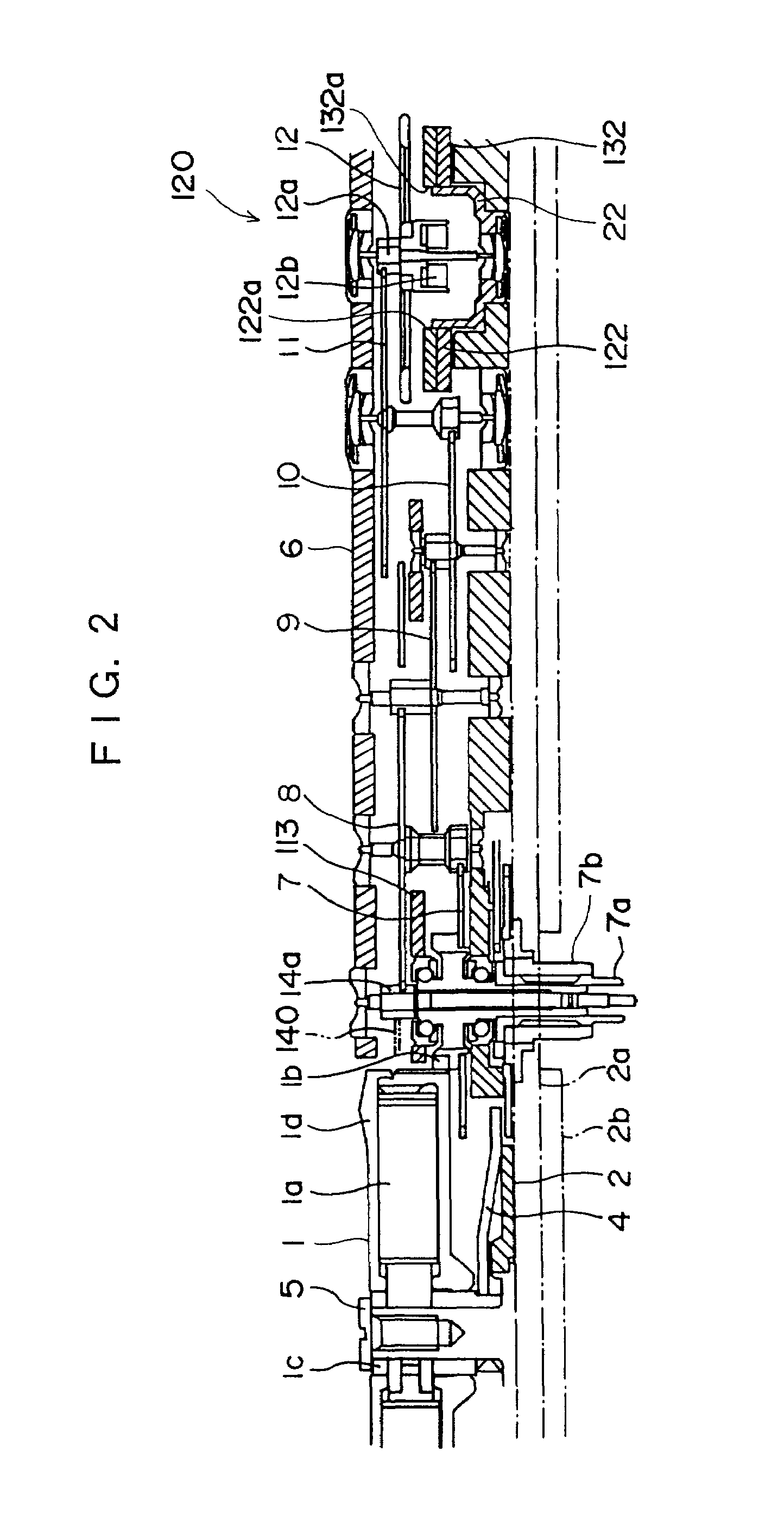
[0111]FIG. 1 is a plan view showing an electronic-controlled mechanical timepiece according to the present invention, and FIGS. 2 and 3 are sectional views of it.
[0112]An electronic-controlled mechanical timepiece is provided with a barrel wheel 1 comprising a mainspring 1a, a barrel gear 1b, a barrel arbor 1c and a barrel case id. The mainspring 1a is fixed to the barrel gear 1b at the outer end of it and fixed to the barrel arbor 1c at the inner end. The barrel arbor 1c in the shape of a sleeve has a support member fitted onto it, the support member being provided on a base plate 2 being in the shape of a flat disk, and is fixed by a square-hole screw 5 to be turned in one with a square-hole wheel 4. And the base plate 2 has a calendar plate 2a and a disk-shaped dial plate 2b attached to it. Symbol 6 in FIGS. 2 and 3 is a gear train holder.
[0113]Hereupon, in this embodiment, a mechanical energy is an elastic force generated by deformation such as flexion of the mainspring 1a when ...
second embodiment
[0138]A second embodiment of the present invention is described with reference to FIGS. 5 and 6.
[0139]In an electronic-controlled mechanical timepiece of this embodiment, the lengths L1 and L2 of the winding cores 123b and 133b are the same as each other (L1=L2), but a winding wound around the winding core 133b is smaller in wire diameter than a winding wound around the winding core 123b. The respective windings are the same as each other in number of turns. And the conductivity of the wire smaller in diameter is larger than the conductivity of the wire larger in diameter.
[0140]This embodiment brings the following effects.
[0141](5) Since a winding wound around the winding core 133b is smaller in wire diameter than a winding wound around the winding core 123b, this embodiment having the same number of turns in the coils 124 and 134 can make the coil 134 smaller in volume by its smaller wire diameter and can make the opening 2c smaller in area. Although this embodiment is different in...
third embodiment
[0142]A third embodiment of the present invention is described with reference to FIGS. 7 and 8.
[0143]In an electronic-controlled mechanical timepiece of this embodiment, the lengths L1 and L2 of the winding cores 123b and 133b are the same as each other (L1=L2), but the width W2 and thickness H2 of the winding core 133b are smaller than the width W1 and thickness H1 of the winding core 123b (W1>W2, H1>H2) and the winding core 133b is made thinner. And the winding core 123b is made of a PC material, whereas the winding core 133b is made of a PB material being larger in saturation magnetic flux density. This embodiment brings the following effects.
[0144](6) Since the winding core 133b is made thinner than the winding core 123b, this embodiment; having the coils 124 and 134 being equal in number of turns and in wire diameter can make the coil 134 smaller in volume by its thinner winding core 133b and can make the opening 2c smaller in area. Although this embodiment is different in comp...
PUM
 Abstract
Description
Claims
Application Information
 - R&D
- Intellectual Property
- Life Sciences
- Materials
- Tech Scout
- Unparalleled Data Quality
- Higher Quality Content
- 60% Fewer Hallucinations
Browse by: Latest US Patents, China's latest patents, Technical Efficacy Thesaurus, Application Domain, Technology Topic, Popular Technical Reports.
© 2025 PatSnap. All rights reserved.Legal|Privacy policy|Modern Slavery Act Transparency Statement|Sitemap|About US| Contact US: help@patsnap.com