
Wafer integrated plasma probe assembly array

a technology of plasma probes and assembly arrays, applied in the field of plasma diagnostic equipment, can solve the problems of probe damage, charge-induced damage in some semiconductor devices,

Inactive Publication Date: 2005-12-06
LAM RES CORP
View PDF15 Cites 12 Cited by
  • Summary
  • Abstract
  • Description
  • Claims
  • Application Information

AI Technical Summary

Benefits of technology

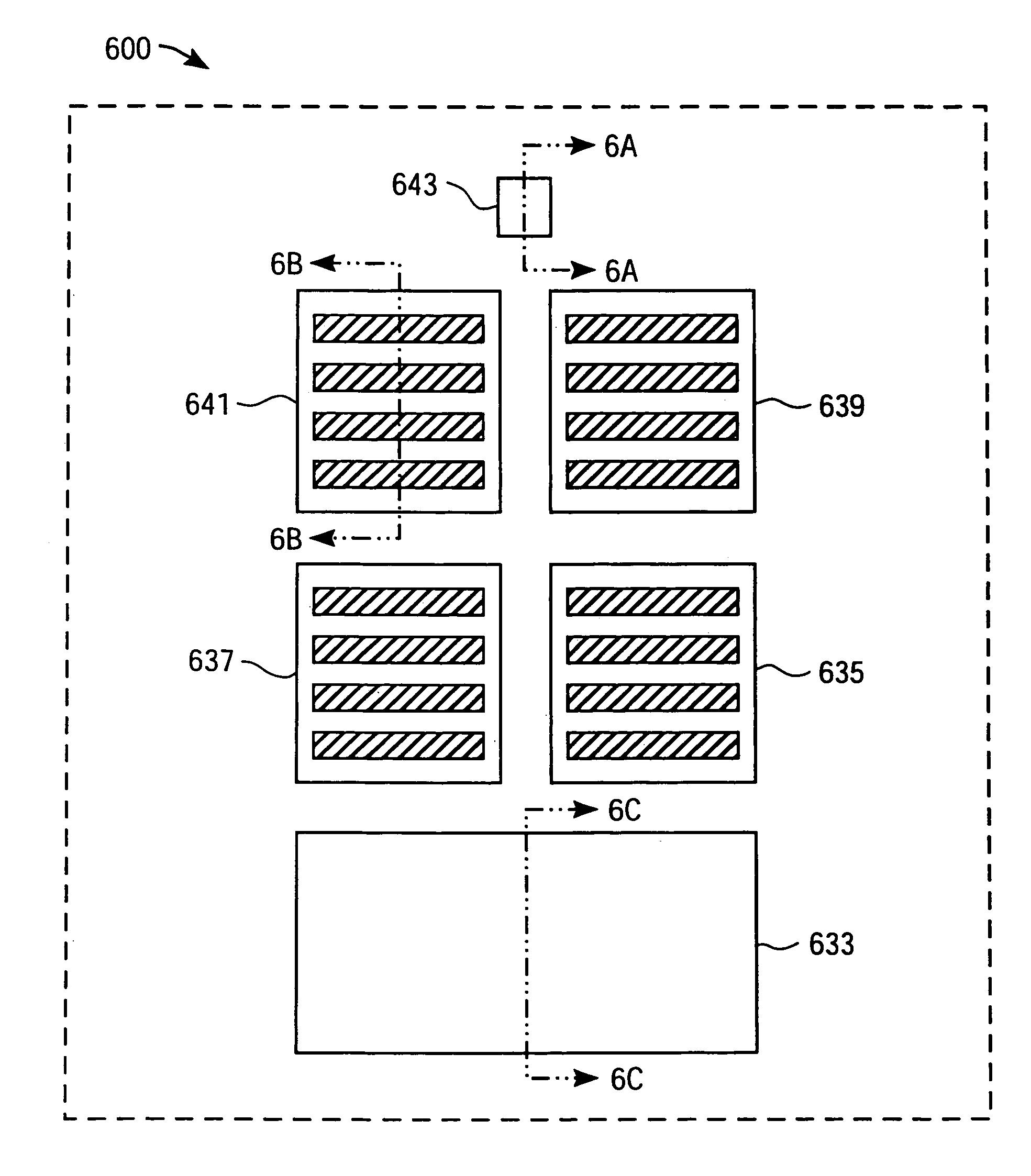
[0018]The probe elements are clustered into an assembly such that four of the six probe elements are of intermediate size or medium size, shaped roughly like squares, and are charge monitors with patterning on them. The structures on the four medium sized probe elements have a non-zero aspect ratio. The four medium sized probe elements are suitable for patterning in different ways to diagnose potentials due to charge shading effects. The probe structures on the four medium sized square elements are rectangular comb-like structures, which don't necessarily have identical aspect ratio. An important aspect of having a range of aspect ratios for the probe elements is that it gives an idea in real time as to what aspect ratio would cause a wafer damage in real time. The presence of probe structures on probe elements determines charge accumulation from the difference in electron and ion currents as they cross the plasma sheath to reach the plasma structures on the wafer substrate. Such a differential electron or ion flux from non-uniform plasmas is responsible for causing charge induced damage in some semiconductor devices. The fifth probe element has an area equal to the four medium sized probe elements and has no patterning on it. An absence of patterning makes the probe a plain probe. The fifth probe element with no patterning is considered to have a zero aspect ratio. The fifth probe element is considered as a reference Langmuir probe and is exposed to the plasma for measurements of floating potential and saturated ion flux. The sixth probe element is a plain probe with no patterning on it. Again, an absence of patterning constitutes zero aspect ratio. The sixth probe element is capable of providing electron measurements. However, the sixth probe element is very much smaller than any probe element or exposed substrate for the reason that in order to perform electron measurements, the excess current could cause damage to the probe if the probe's area is bigger because the probes are essentially made of conductors. The sixth probe element is a novel addition to any of the prior art in plasma diagnostics as it allows electron measurements along with flux, potential and charging damage measurements performed simultaneously in real time.

Problems solved by technology

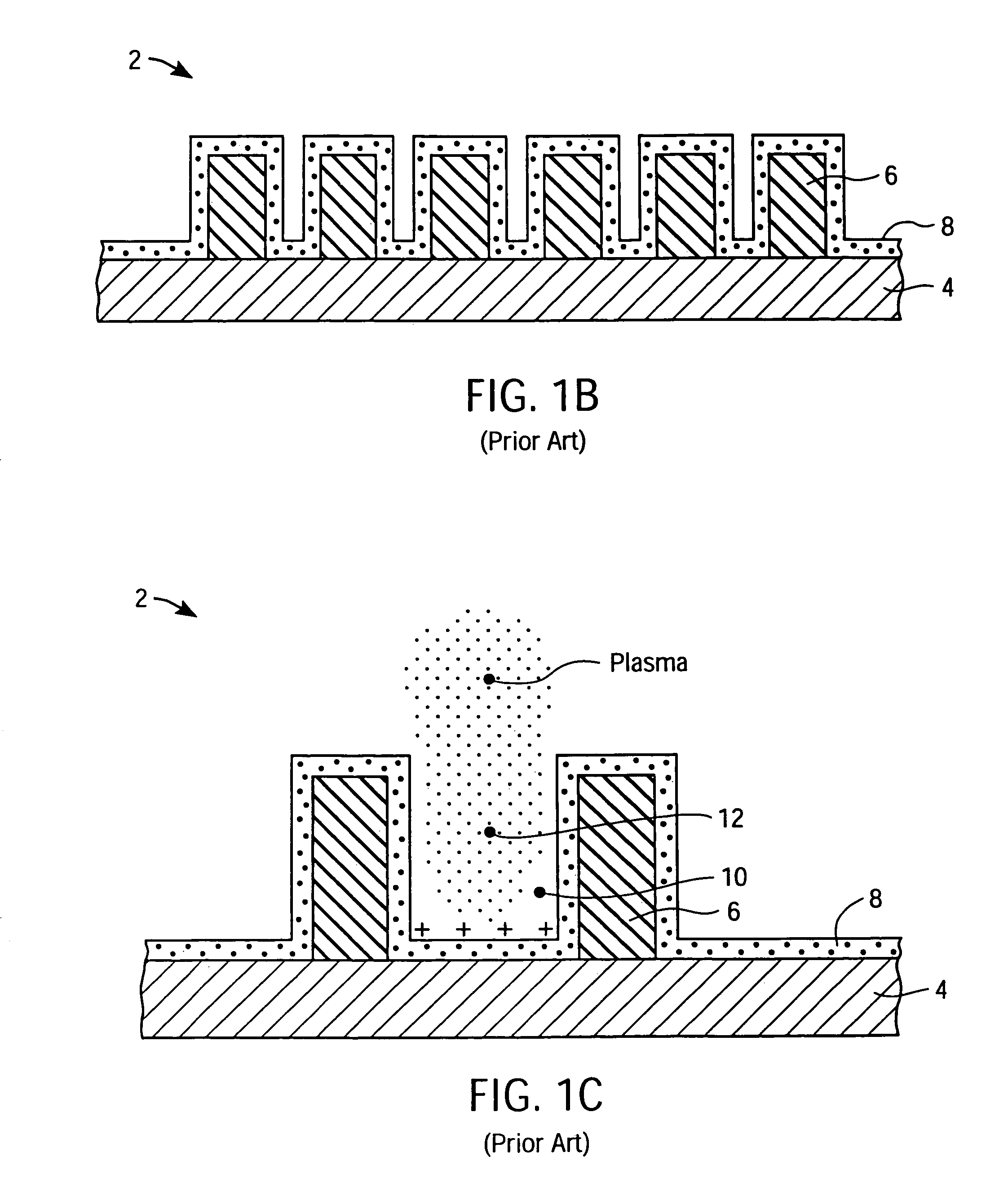
Such a differential electron or ion flux from non-uniform plasmas is responsible for causing charge induced damage in some semiconductor devices.
However, the sixth probe element is very much smaller than any probe element or exposed substrate for the reason that in order to perform electron measurements, the excess current could cause damage to the probe if the probe's area is bigger because the probes are essentially made of conductors.

Method used


Image

  • Wafer integrated plasma probe assembly array
  • Wafer integrated plasma probe assembly array
  • Wafer integrated plasma probe assembly array

Examples


Embodiment Construction

[0033]An invention is disclosed for simultaneous measurement of shading induced potentials, ion fluxes, ion energy distribution, and the electron part of the I-V Langmuir probe characteristic. The present invention makes it possible to simultaneously measure several plasma characteristics in real time across a wide area of the wafer surface while the semiconductor wafer is inside of the plasma chamber. In the following description, numerous specific details are set forth in order to provide a thorough understanding of the present invention. It will be apparent, however, to one skilled in the art, that the present invention may be practiced without some or all of these specific details. In other instances, well known process steps have not been described in detail to avoid obscuring the present invention unnecessarily.

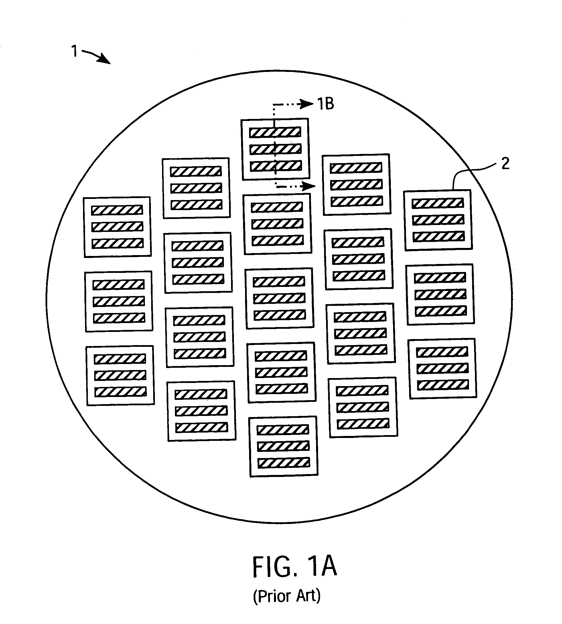
[0034]FIGS. 1 and 2 were described in terms of the prior art. FIG. 3 is an illustration of a planar Langmuir probe 300 in accordance with one embodiment of the present ...


PUM


Abstract

A wafer integrated plasma diagnostic apparatus for semiconductor wafer processing system having a multiplicity of plasma probe assemblies arranged on a wafer in a planar array fashion such that one plasma probe assembly is in the center and eight more plasma probe assemblies are at intermediate positions such that they lie along the radius from the center to the corners; such corners forming four corners of a square box near the edge of the wafer. At each location and in each of the plasma probe assemblies, there are six possible probe elements having a relative geometrical area such that they are capable of making simultaneous measurements of both spatial resolution and real time measurement of different plasma characteristics at the wafer surface, such as: D.C. potential, A.C. potential, shading induced potentials, ion fluxes, ion energy distribution, and the electron part of the I-V Langmuir probe characteristic.

Description

CROSS REFERENCE TO RELATED APPLICATIONS[0001]This application is a continuation application claiming 35 U.S.C. § 120 priority from parent U.S. patent application Ser. No. 10 / 680,791, filed Oct. 6, 2003 now U.S. Pat. No. 6,781,393, entitled “METHODS RELATING TO WAFER INTEGRATED PLASMA PROBE ASSEMBLY ARRAYS,” which parent Application is herein incorporated by reference. The parent Application is a Divisional application which claimed 35 U.S.C. § 120 priority from its parent U.S. patent application Ser. No. 09 / 540,418, filed Mar. 31, 2000, entitled “WAFER INTEGRATED PLASMA PROBE ASSEMBLY ARRAY,” issued Nov. 11, 2003, as U.S. Pat. No. 6,653,852, which patent is herein incorporated by reference.FIELD OF THE INVENTION[0002]The present invention relates generally to plasma diagnostic apparatuses for semiconductor wafer processing systems. More particularly, the present invention relates to a wafer integrated plasma probe assembly array.BACKGROUND OF THE INVENTION[0003]In the semiconductor ...

Claims


Application Information

Patent Timeline
IPC IPC(8): H01L23/544
CPCH01L22/34H01L2924/3011H01L2924/0002H01L2924/00
Inventor BENJAMIN, NEIL
Owner LAM RES CORP
Learn More