Eureka AIR delivers breakthrough ideas for toughest innovation challenges, trusted by R&D personnel around the world.

Method for detecting a change in permeability of a magnetostrictive object

a magnetostrictive object and change of permeability technology, applied in the field of magnetic permeability, can solve the problems of inaccuracy in determining the change of permeability of the object, and adds to the cost and space requirements of making such measurements

Inactive Publication Date: 2005-12-06
DELPHI TECH INC +1
View PDF25 Cites 5 Cited by
  • Summary
  • Abstract
  • Description
  • Claims
  • Application Information

AI Technical Summary

Benefits of technology

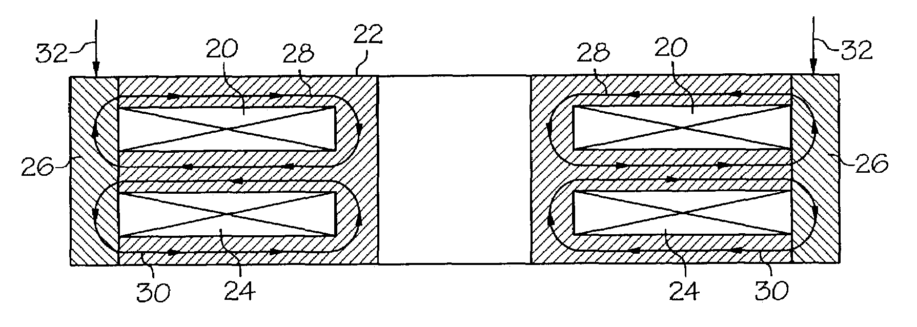
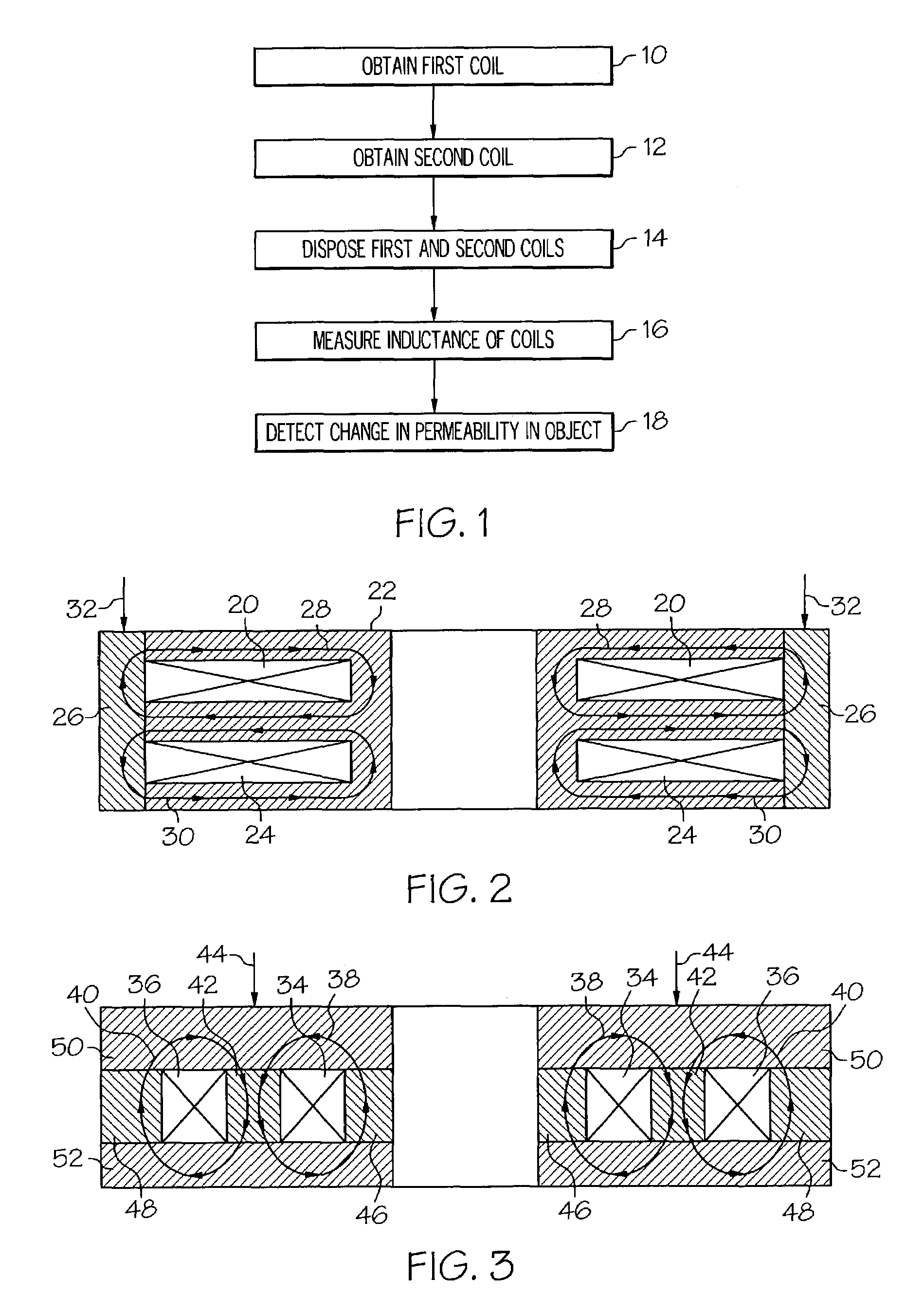
[0009]FIG. 2 is a schematic cross-sectional view of a first embodiment of apparatus which can be used in the performance of the first method; a

Problems solved by technology

Such magnetic noise sensed by the coil leads to an inaccurate determination of a change in permeability of the object.
A conventional approach to reducing such magnetic noise when detecting a change in permeability of the object is to install magnetic shielding which adds to the cost and space requirements for making such measurements.

Method used


Image

  • Method for detecting a change in permeability of a magnetostrictive object
  • Method for detecting a change in permeability of a magnetostrictive object

Examples


first embodiment

[0021]apparatus which can be used to carry out any of the above methods is shown schematically in FIG. 2. The circular first coil 20 is disposed in a first recess of an optional ferromagnetic bobbin 22, and the circular second coil 24 is disposed in a second recess of the ferromagnetic bobbin 22. The magnetostrictive object 26 in this embodiment is a circular ring. The outer circumference of the first and second coils 20 and 24 is disposed in contact with the inner circumference of the ring. In one choice of materials, the object 26 consists essentially of nickel. Other choices of materials for the ferromagnetic object 26 are left to the artisan. The first and second coils 20 and 24 are connected in series (such connection being omitted from FIG. 2 for clarity). The first coil 20 has turns wound in an opposite direction to the turns of the second coil 24. The magnetic flux lines 28 induced by the alternating electric current in the first coil 20 are shown as a single loop with arrow...

second embodiment

[0022]apparatus which can be used to carry out any of the above methods is shown schematically in FIG. 3. The first coil 34 and the second coil 36 are disposed as shown. The magnetic flux lines 38 of the first coil 34 and the magnetic flux lines 40 of the second coil 36 are shown as loops “running” in opposite directions wherein the magnetic flux lines 38 and 40 pass each pass through a portion of the magnetostrictive object 42 in a direction parallel to (and the same as) the strain direction 44. The apparatus also includes other magnetostrictive rings 46 and 48 and upper and lower steel annular bands 50 and 52 as shown. Still other embodiments of apparatus to carry out any of the above methods are left to the artisan in view of the above teachings.

[0023]Several benefits and advantages are derived from one or more of the methods of the invention. By using at least one first coil and at least one second coil which together substantially cancel out electromagnetic interference, a more...


PUM


Abstract

A method for detecting a change in permeability of a magnetostrictive object due to a change in strain. At least one first coil and at least one second coil are obtained and positioned such that magnetic flux lines induced by an electric current in the first coil(s) pass through at least one portion of the object in a direction substantially parallel to the strain direction, such that magnetic flux lines induced by an electric current in the second coil(s) pass through at least one portion of the object in a direction substantially parallel to the strain direction, and such that any electromagnetic interference sensed by the first coil(s) is sensed oppositely by the second coil(s). The total inductance of the positioned first and second coil(s) is measured over time. A change in permeability of the object is detected from a change in the measured total inductance over time.

Description

TECHNICAL FIELD[0001]The present invention relates generally to magnetic permeability, and more particularly to a method for detecting a change in permeability of a magnetostrictive object due to a change in strain in the object.BACKGROUND OF THE INVENTION[0002]Conventional methods for determining a change in permeability of a magnetostrictive object due to a change in strain in the object include using an inductive coil. The coil is positioned relative to the object such that magnetic flux lines induced by an alternating electric current in the coil pass through the object in a direction substantially parallel to the strain direction. The inductance of the coil is measured over time. A change in permeability of the object is detected or determined from a change in the measured inductance over time. The coil also senses electromagnetic interference from sources outside the object being measured such as from nearby motors and electronic equipment when the object is located in a magne...

Claims


Application Information

Patent Timeline
IPC IPC(8): G01B7/24G01L1/12G01R33/12G01R33/18
CPCG01B7/24G01R33/1223G01L1/127G01L1/125G01R33/18
Inventor BAUDENDISTEL, THOMAS A.DISSER, ROBERT J.CYRAN, CURTIS
Owner DELPHI TECH INC
Why Eureka
Eureka Blog
Learn More