
Fast change transformer connector and adaptor

a transformer connector and fast-changing technology, applied in the direction of transformer/coil connectors, coupling device connections, electrical apparatus, etc., can solve the problems of difficult access to the cable end lug closest to the stud of the spade connector, inconvenient and difficult detachment of the transformer connector

Inactive Publication Date: 2005-12-06
WALTON CHRISTOPHER E
View PDF3 Cites 24 Cited by
  • Summary
  • Abstract
  • Description
  • Claims
  • Application Information

AI Technical Summary

Benefits of technology

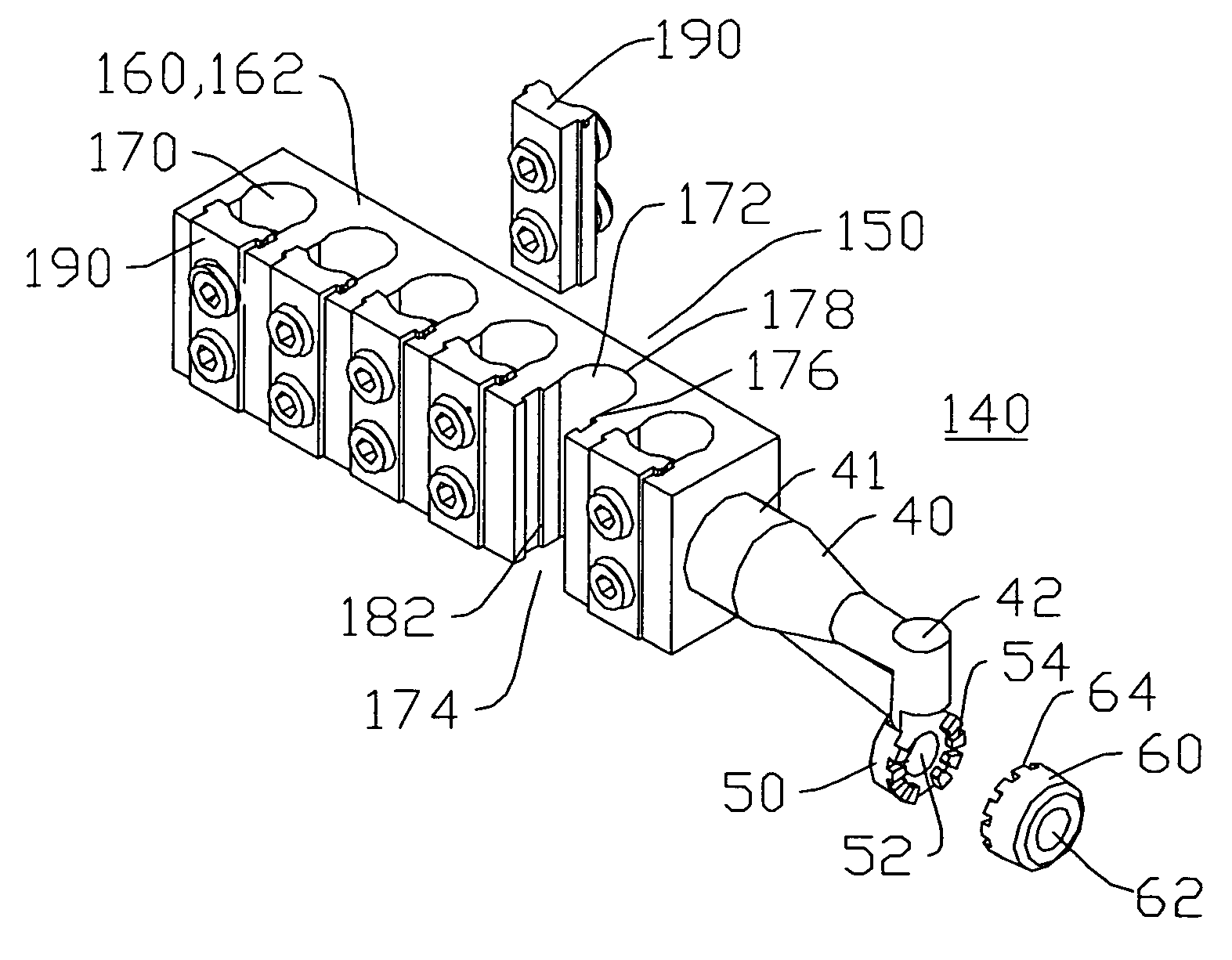
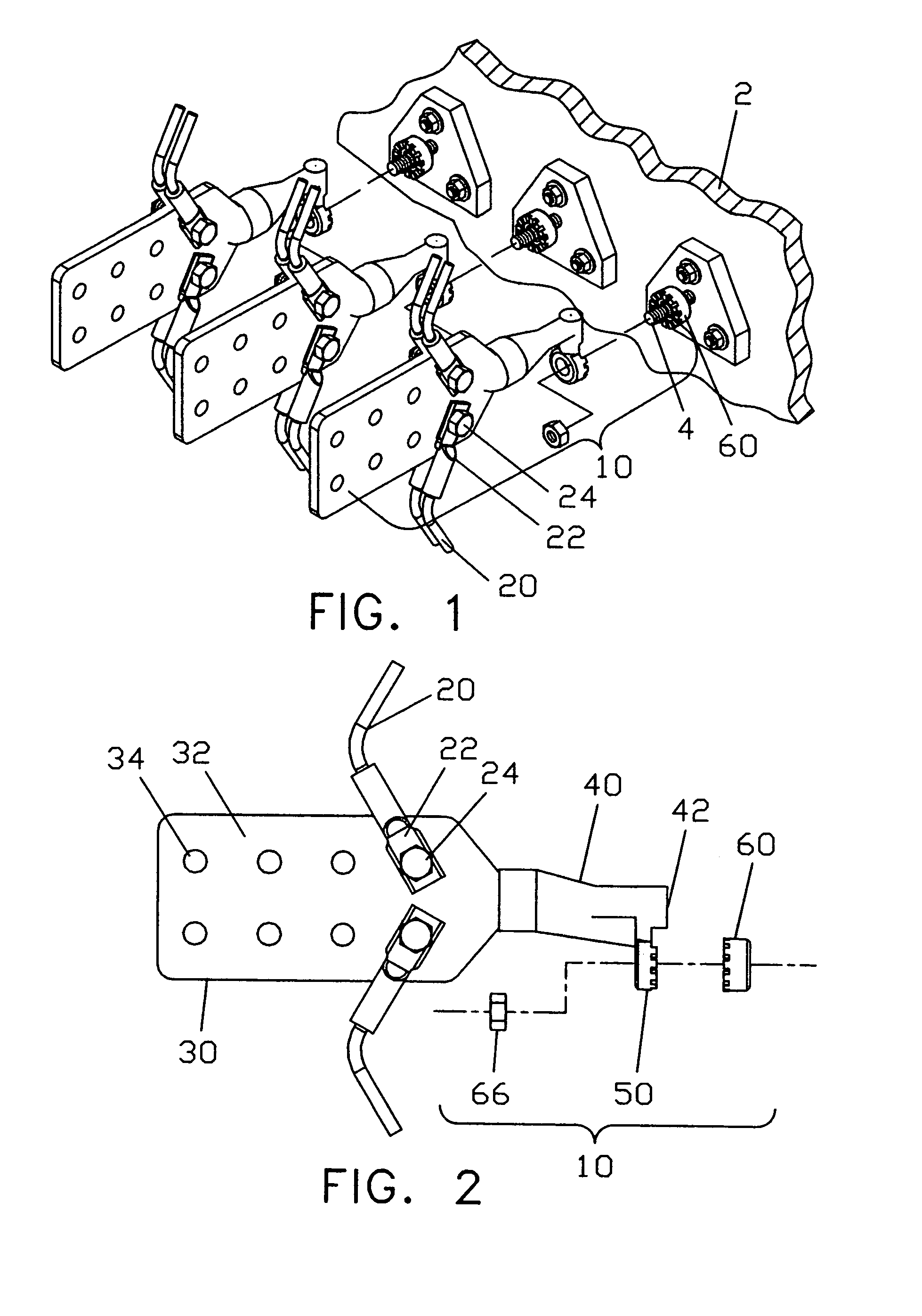
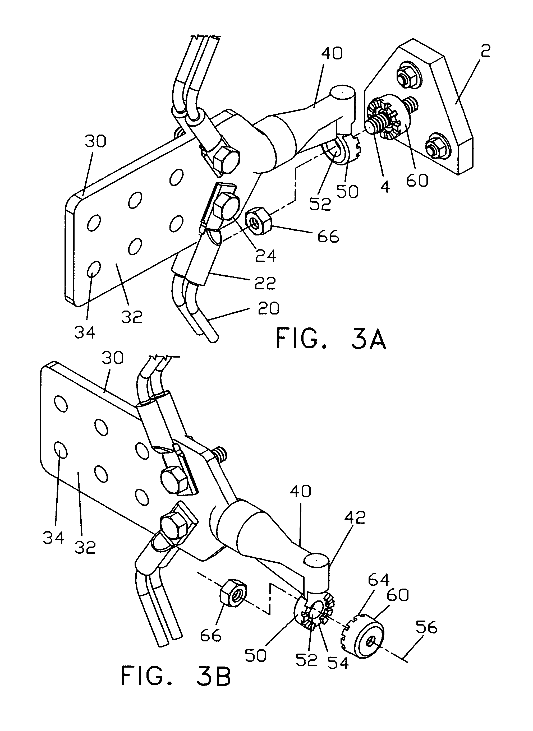
[0013]In one embodiment, the present invention provides transformer connectors which enable fast replacement of an electric transformer without disconnecting electrical cables. The transformer connector comprises a cable connector having a cable attachment body with a plurality of cable attachment ports, a connector extension with the first end connected to the cable attachment body, and a stud slide adaptor connected to a side of the connector extension near the second end; and a stud screw adaptor having a threaded opening complimentary to a transformer stud, for connecting the transformer stud and the stud slide adaptor of the cable connector.
[0016]In another embodiment, the present invention provides a transformer adaptor, which can, be used to connect an electrical cable connector to a transformer stud. The transformer adaptor comprises an inter-connector comprising a connecting shaft having screw threads at one end; and a stud slide adaptor connected to a side of the connecting shaft at the opposing end; and a stud screw adaptor having a threaded opening complimentary to a transformer stud, for connecting the transformer stud and the stud slide adaptor of the inter-connector. The transformer adaptor of the present invention can be used with existing transformer connectors, such as spade connectors, for conveniently detach the transformer connectors without disconnecting the electrical cables. Furthermore, the transformer adaptor can also comprise an adaptor extension, as described above, for connecting the inter-connector to the transformer.

Problems solved by technology

Moreover, each disconnected cable has to be grounded immediately for safety reasons.
Furthermore, the cable end lug closest to the stud on the spade connector are relatively difficult to access.
Even worse, the inner set bolts may not be readily visible, forcing the electrician to work blindly.
Still further, bolts might have become corroded causing extreme difficulty in removing the cables.
It is apparent that this is a lengthy and labour intensive process.
Such a connection is not as secure as the connection of a traditional spade connector, which is directly bolted on to the transformer stud.
For a long term use, the connection between aluminum and brass tends to become loose, causing poor connection between the transformer and the connector.

Method used


Image

  • Fast change transformer connector and adaptor
  • Fast change transformer connector and adaptor
  • Fast change transformer connector and adaptor

Examples


second embodiment

[0044]In the second embodiment, the present invention is related to a transformer adaptor. As shown in FIG. 6, transformer adaptor 70 comprises an inter-connector 80, and a stud screw adaptor 60 for connecting inter-connector 80 and transformer stud 4. The inter-connector 80 includes a connecting shaft 82 which has embedded male screw threads at one end 84, also called cable end; and a stud slide adaptor 50 connected to a side of said connecting shaft at the opposing end 86, also called transformer end. The transformer adaptor 70 further includes a bolt nut 66 which is described previously.

first embodiment

[0045]The structures of stud slide adaptor 50 and stud screw adaptor 60 of transformer adaptor 70, and the mechanism of connection to transformer 2 are the same as those of transformer connector 10 described in detail in the

[0046]As illustrated in FIGS. 8 and 9, transformer adaptor 70 is used to connect a cable connector which has embedded female screw threads within the body of the cable connector, which is commonly used for connecting to transformer stud 4. FIG. 8 shows the female adapting end 92 of a traditional spade connector 90. Traditionally, to connect spade connector 90 onto transformer 2, an electrician turns spade connector 90 around transformer stud 4, and then attach cables 20 to spade connector 90. To disconnect spade connector 90 from transformer 2, the electrician has to disconnect each individual cable 20 before spade connector 90 can be turned around transformer stud 4 in the opposite direction.

[0047]With transformer adaptor 70 of the present invention, one can con...


PUM


Abstract

A fast change electric transformer connector is disclosed, which includes a cable connector having a cable attachment section, a connector extension connected to the cable attachment section, and a stud slide adaptor connected to a side of the connector extension for slidably attaching the cable connector to a transformer stud; and a stud screw adaptor complimentary to a transformer stud. The cable attachment section includes a cable receiving body having multiple receiving slots for receiving cables; and multiple removable sliding cable fastening blocks disposed within the receiving slots for fastening the cables. Each sliding cable fastening block can be slid in or out from the receiving slot for conveniently installing a large cable. Also disclosed are a transformer connector and a transformer adaptor, which have an adaptor extension for connecting between the transformer stud and the cable connection portion of the connector / adaptor, for use when shorted cables are cut.

Description

REFERENCE TO RELATED APPLICATION[0001]This application is a continuation-in-part application of patent application Ser. No. 10 / 305,859, filed Nov. 27, 2002, now U.S. Pat. No. 6,837,754 which is hereby incorporated by reference in its entirety.FIELD OF THE INVENTION[0002]The present invention relates to the field of electric power distribution, and, more specifically, to fast change transformer connectors, which enable changing a transformer without disconnecting electric cables from the connectors.BACKGROUND OF THE INVENTION[0003]Transformers are key components presently in electric power distribution networks. Generally, electric power is distributed from electrical substations at high voltage typically in excess of 6,000 volts to minimize losses. Transformers are required to reduce the voltage down to lower levels, such as 120 volts, for local distribution to commercial and residential customers.[0004]A transformer commonly used for this purpose is housed in a steel cabinet on a c...

Claims


Application Information

Patent Timeline
Patent Type & Authority Patents(United States)
IPC IPC(8): H01R11/12H01R31/06
CPCH01R11/12H01R31/06H01R2201/22Y10S439/957
Inventor WALTON, CHRISTOPHER E.
Owner WALTON CHRISTOPHER E
Learn More