
Complex impedance spectrometer using parallel demodulation and digital conversion

a technology of complex impedance spectrum and demodulation, applied in the field of analytical instruments, can solve the problems of limited method, limited system bandwidth, and difficulty in electronic circuit design for bandwidths larger than 1 mhz

Active Publication Date: 2005-11-29
CRITICAL PERFUSION
View PDF25 Cites 45 Cited by
  • Summary
  • Abstract
  • Description
  • Claims
  • Application Information

AI Technical Summary

Benefits of technology

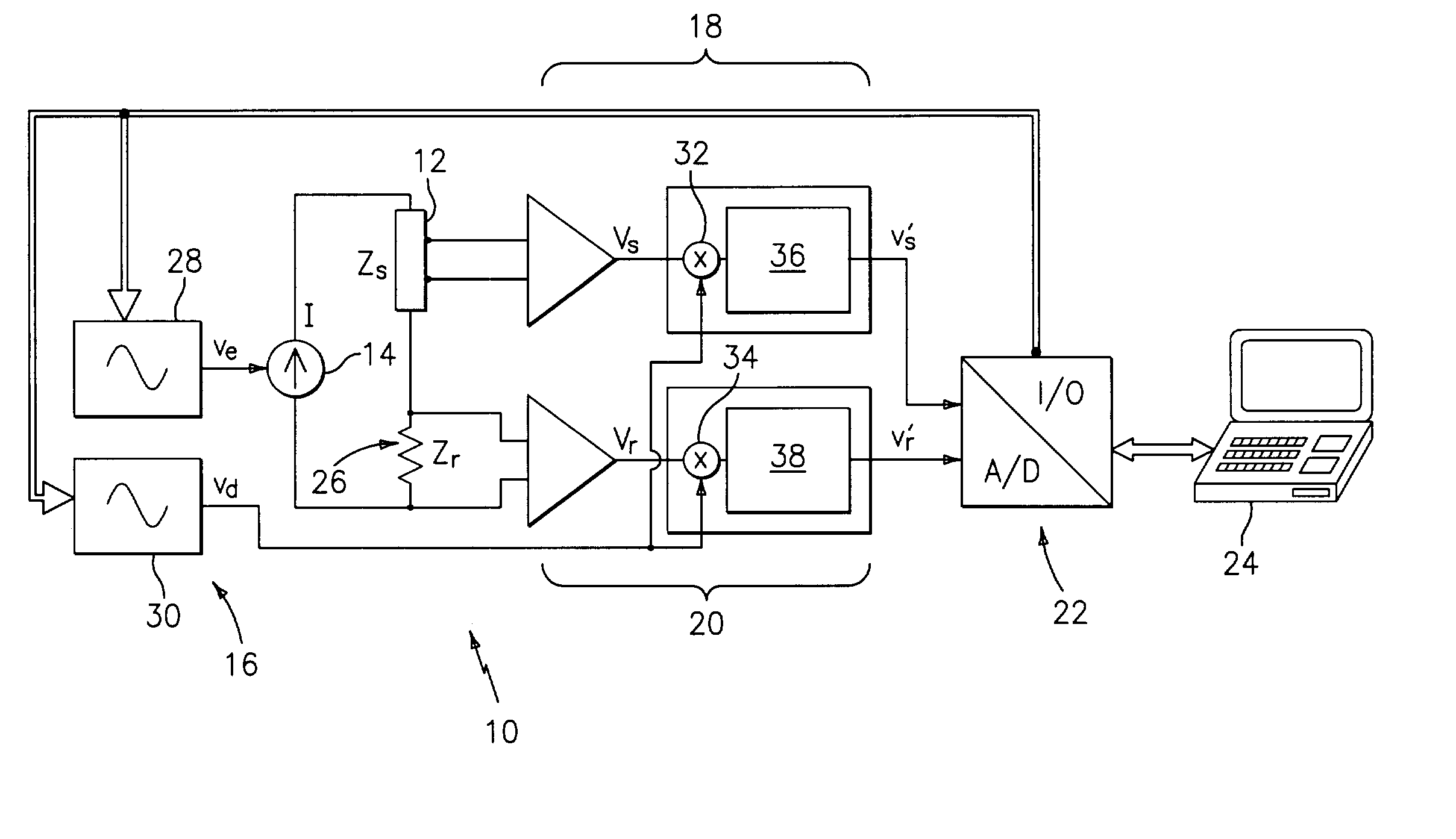
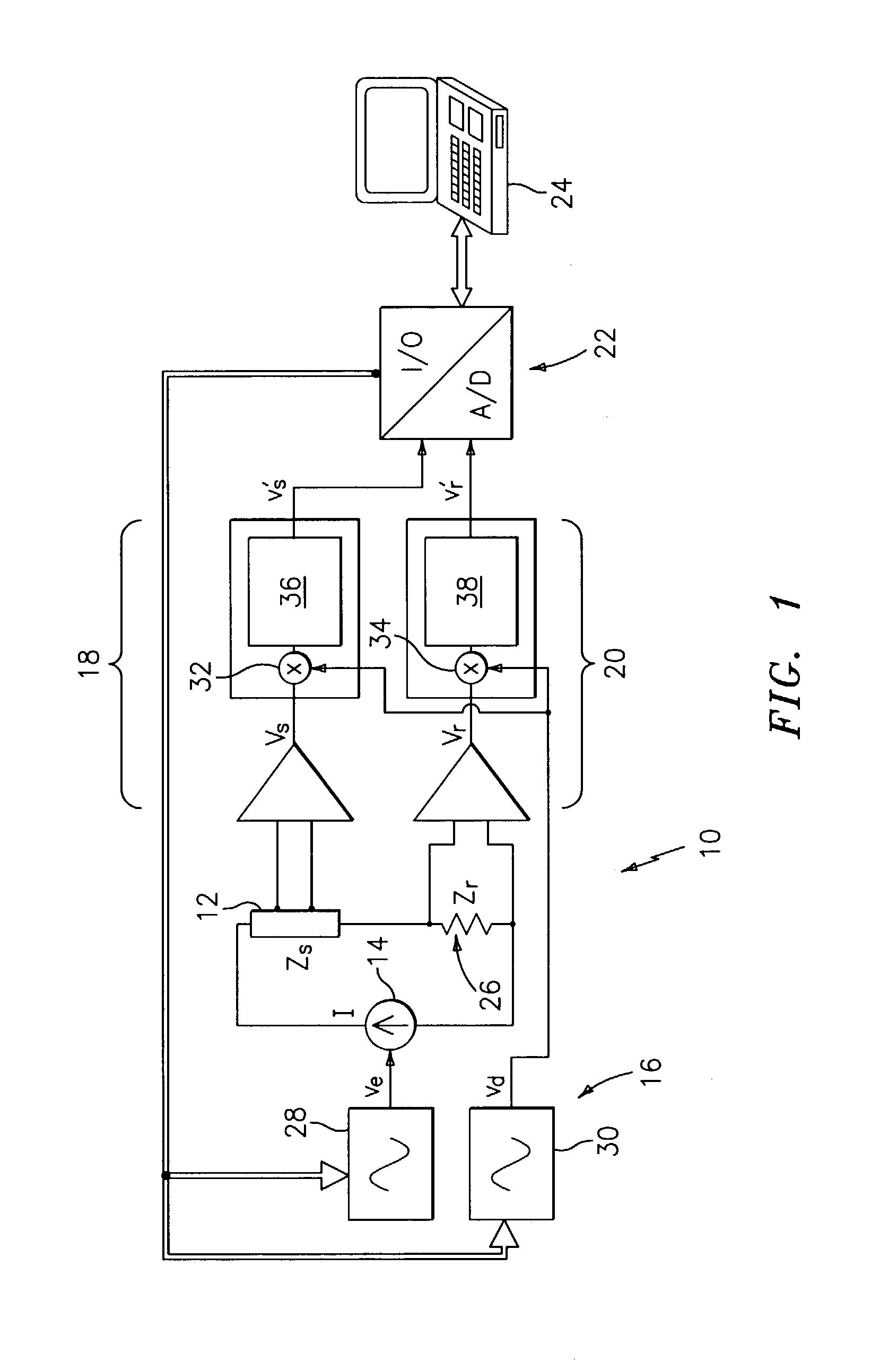
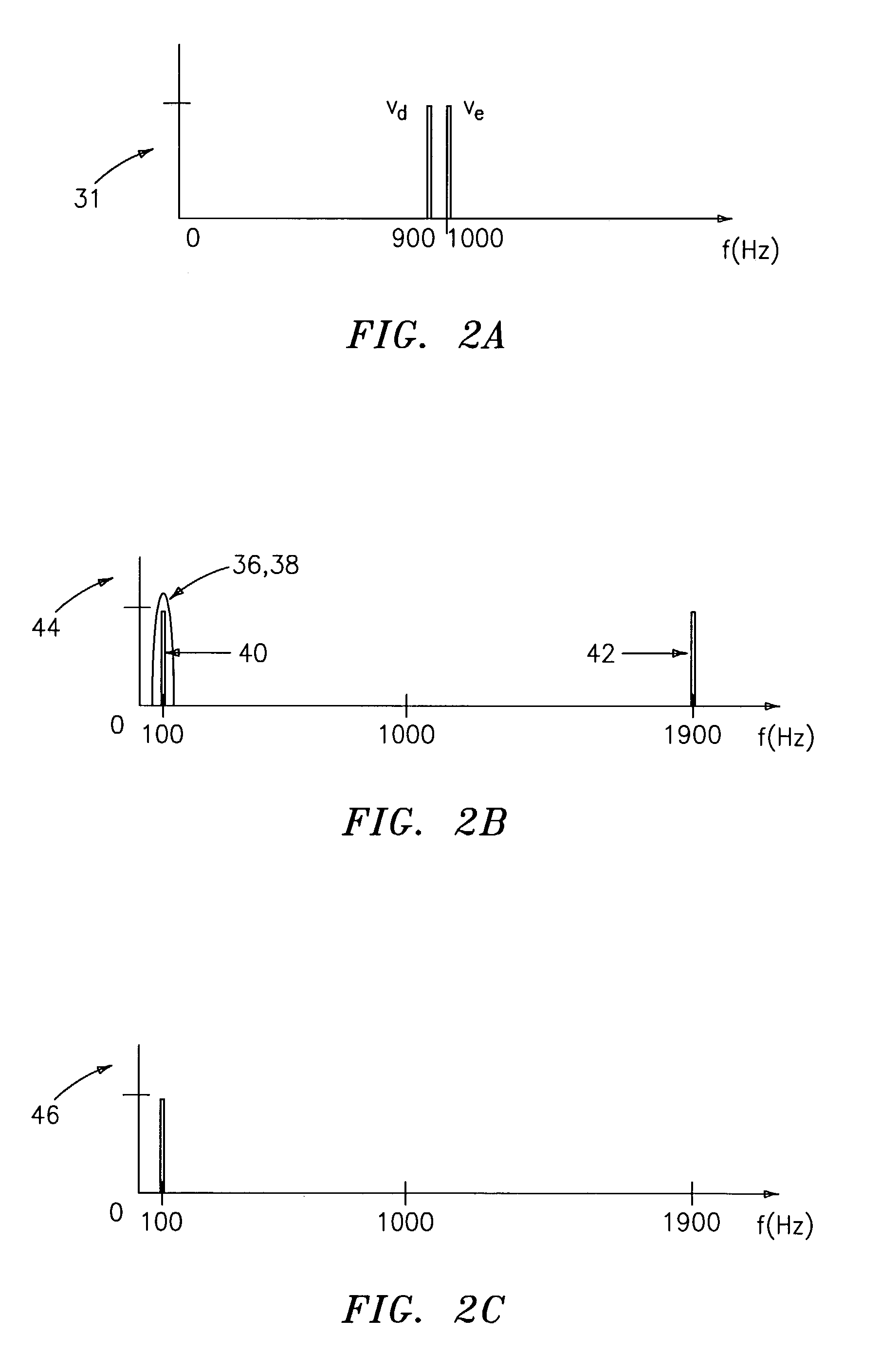
[0009]A high-bandwidth spectrometer for measuring the complex impedance spectrum of tissue or other objects or systems comprises: a multi-frequency excitation current generator; a demodulation signal generator; two identical amplification and demodulation circuits; a two channel A / D converter; and a microprocessor or personal computer for signal processing, recording, and / or display. The current generator is used to excite the system or sample being analyzed, as well as a reference impedance connected in series. The voltages generated in the sample and in the reference impedance are measured, demodulated, and digitized in parallel using the two amplification and demodulation circuits (in conjunction with the demodulation signal generator) and the A / D converter. The signals are demodulated using the same demodulation signal generated at a frequency with a preset difference from the excitation signal. This demodulation allows all measurements to be made at the same low frequency independent of the excitation frequency. By making use of the relatively high sampling frequency of the A / D converter (even the most inexpensive analog-to-digital converters available today have high sampling frequencies), the signals are captured with their relative amplitude and phase information intact, and without the need for any synchronization or timing circuitry. The complex impedance spectrum of the sample is then calculated in relation to the reference signal with software in the microprocessor or personal computer. Because the measurements are relative, they are independent of both the amplitude of the excitation current and the phase of either the excitation or the demodulation signals, and are therefore very accurate.

Problems solved by technology

This method is limited at high frequencies, however, to the rise time and sampling frequency of the electronics used, and is disadvantageous in that the electronic circuit design becomes difficult for bandwidths larger than 1 MHz.
However, this system requires precise synchronization between the two A / D channels to facilitate accurate phase measurements, and the bandwidth of the system is limited by the sampling frequency of the A / D converters.
However, synchronization circuits can be expensive and / or difficult to implement, rendering systems that require them less than fully ideal.

Method used


Image

  • Complex impedance spectrometer using parallel demodulation and digital conversion
  • Complex impedance spectrometer using parallel demodulation and digital conversion
  • Complex impedance spectrometer using parallel demodulation and digital conversion

Examples


Embodiment Construction

[0018]Turning now to FIGS. 1–4, a preferred embodiment of a method and system 10 for measuring the complex impedance spectrum of tissue or some other sample 12, according to the present invention, will now be given. The system 10 (also sometimes referred to as a spectrometer) generally comprises: a multi-frequency excitation current generator 14; a demodulation signal generator 16; two identical amplification and demodulation circuits 18, 20; and a signal processor and / or control device 21 (signal processing means) comprising a two channel A / D converter 22 and a microprocessor or personal computer 24 for signal processing, recording, and / or display. The current generator 14 is used to excite the sample 12 being analyzed, as well as a reference impedance 26 electrically connected to the sample 12 in series. The voltage Vs generated in the sample 12 and the voltage Vr generated in the reference impedance 26 are measured, demodulated and digitized in parallel, and the complex impedance...


PUM


Abstract

A spectrometer for measuring the complex impedance spectrum of tissue comprises: a multi-frequency excitation current generator; a demodulation signal generator; two identical amplification / demodulation circuits; an A / D converter; and a microprocessor for signal processing. In use, the current generator excites the tissue sample and a series-connected reference impedance. The voltages generated in the tissue and reference are measured, demodulated, and digitized in parallel using the demodulation signal generator, the two amplification / demodulation circuits, and the A / D converter. Demodulation is done using the same demodulation signal generated at a frequency with a preset difference from the excitation signal, which allows measurements to be made at a low frequency independent of the excitation frequency. The microprocessor then calculates the complex impedance spectrum in relation to the reference signal. Because the measurements are relative, they are independent of both the excitation current amplitude of the phase of the excitation and demodulation signals.

Description

[0001]This application claims priority from a Provisional Application, Ser. No. 60 / 354,453, filed Feb. 4, 2002.FIELD OF THE INVENTION[0002]The present invention relates to analytical instruments, and, more particularly, to devices for measuring the complex impedance spectrum of tissue or other objects or systems.BACKGROUND OF THE INVENTION[0003]Complex impedance spectrometry is used in a variety of applications including transmission line and biomedical tissue analysis. Impedance spectrometry measurements are either made in the time domain or the frequency domain. In the time domain, impedance spectrometry is performed by exciting the sample or system to be analyzed with an electric current pulse and measuring the resulting deformed voltage pulse. The complex impedance spectrum can then be calculated by applying a Fast-Fourier Transform or other spectral analysis algorithms to the measured pulse time series. The basic method was described by P. J. Hyde in 1970, and further embodimen...

Claims


Application Information

Patent Timeline
Patent Type & Authority Patents(United States)
IPC IPC(8): A61B5/05A61B5/053G01R27/02
CPCA61B5/053G01R27/02
Inventor OTHMAN, SALAHSACRISTAN ROCK, EMILIO
Owner CRITICAL PERFUSION
Learn More