
Method and apparatus for extending operating range of bar code scanner

Inactive Publication Date: 2005-11-29
HAND HELD PRODS
View PDF85 Cites 170 Cited by
  • Summary
  • Abstract
  • Description
  • Claims
  • Application Information

AI Technical Summary

Benefits of technology

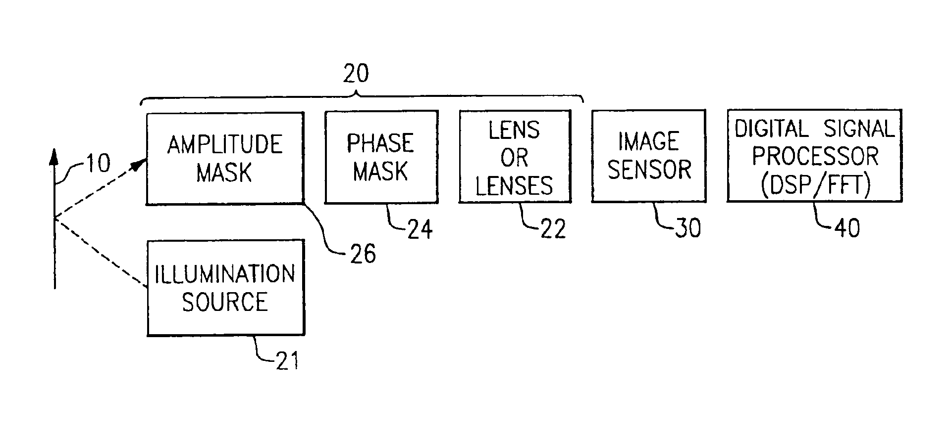
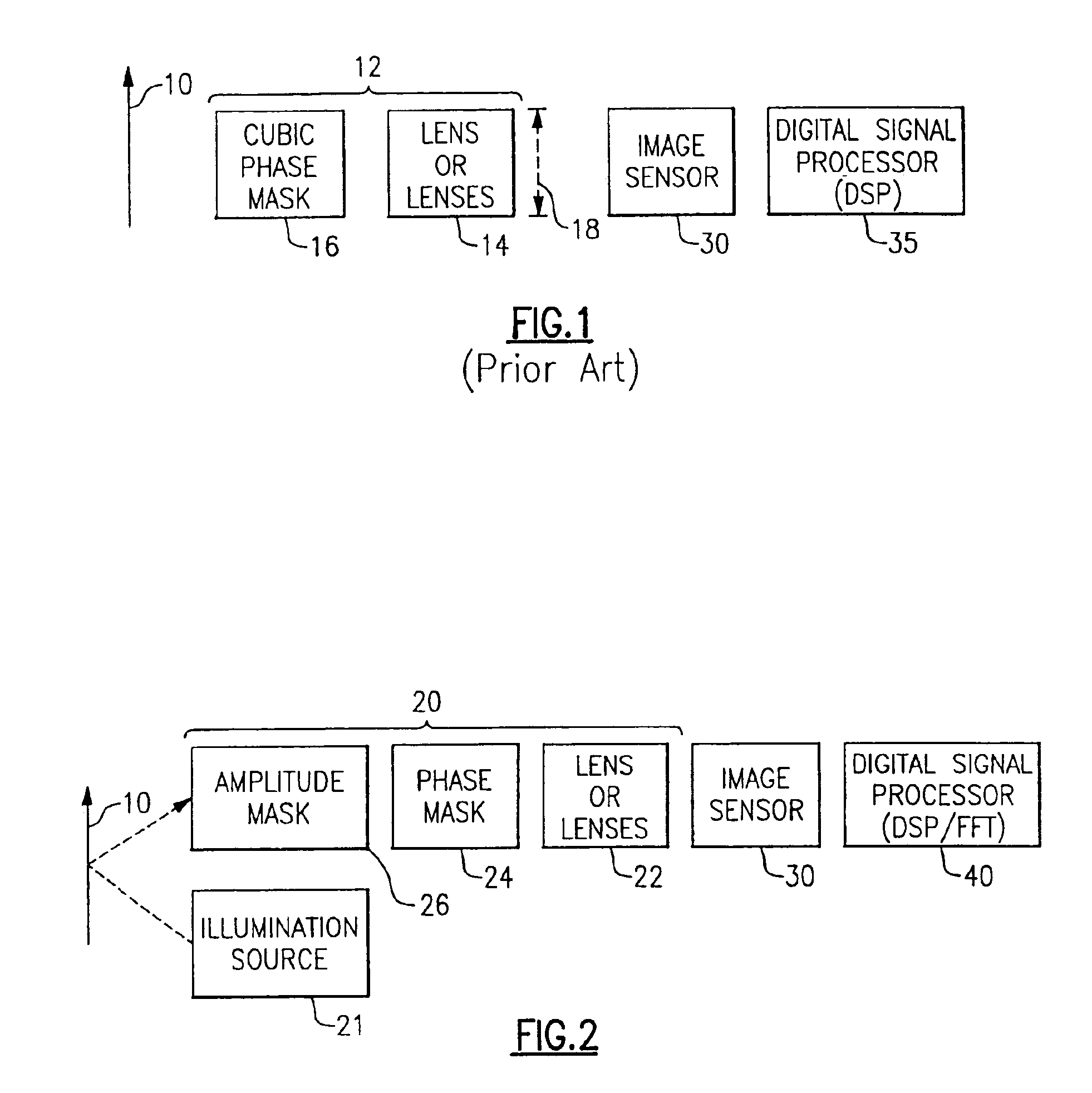
[0016]According to an embodiment of the invention, an imaging system for imaging an object located in a target region includes an illumination source; an optical path between the illumination source and the object; a first optics assembly in the optical path; phase masking means in the optical path for receiving light and modifying a phase thereof as a function of position within the phase masking means, thereby creating phase modified light having known effects therein; means for traversing the phase modified light across the object in the target region; image sensing means for receiving light reflected from the object and producing an intermediate image signal therefrom; the intermediate image signal having at least a misfocus error that is dependent upon a distance between the first optics assembly and the object; and processing means for correcting for the known effects of the phase modified light to produce a final image signal of the object. The final image thus has a reduced amount of out of focus error over a range of distances.
[0018]According to an embodiment of the invention, a method of modifying a laser beam to maximize the system resolving ability as a bar code indicia is moved throughout an operational depth of field includes the steps of (a) generating a laser illumination beam; (b) modifying a phase of the illumination beam a function of position in the beam; (c) modifying an amplitude of the illumination beam as a function of position in the beam; (d) scanning the phase and amplitude-modified beam across the bar code indicia; (e) receiving light reflected from the bar code indicia; (f) converting the received light to an intermediate image signal; and (g) processing the intermediate image signal using a precalculated recovery function to reduce effects of a position of the bar code indicia.
[0020]According to an embodiment of the invention, a method of increasing an operating depth of field includes (a) providing illumination; (b) distorting a phase of the illumination in a predetermined manner at a specific distance from an object; (c) directing the distorted illumination to the object; (d) receiving light scattered from the object; (e) converting the received light to an intermediate image signal; and (f) processing the intermediate image signal using a precalculated recovery function to reduce effects of the specific distance.

Problems solved by technology

However, the possible distances are limited by the depth of field (DOF).
With such fixed focus systems, there is typically a “dead zone” in front of the scanner in which the spot size is too large for proper operation.
This step is a relatively costly one, adding to the cost of manufacturing the laser scanner.
The errors and distortions introduced by the imaging system include, among others, lens aberrations, such as spherical and chromatic aberrations, misfocus errors resulting from an object being located away from the position of best focus, diffraction effects produced by aperture stops, and the diffusion effect associated with some indicia substrates.
While all of these approaches achieve some improvement in image quality, they all have features that limit their usefulness in particular applications, such as bar code reading.
While the image correcting technique described above produces results that are substantially better than the results produced by purely optical means, our efforts to use phase masks in imaging type optical readers using this technique have produced unsatisfactory results.

Method used


Image

  • Method and apparatus for extending operating range of bar code scanner
  • Method and apparatus for extending operating range of bar code scanner
  • Method and apparatus for extending operating range of bar code scanner

Examples


first embodiment

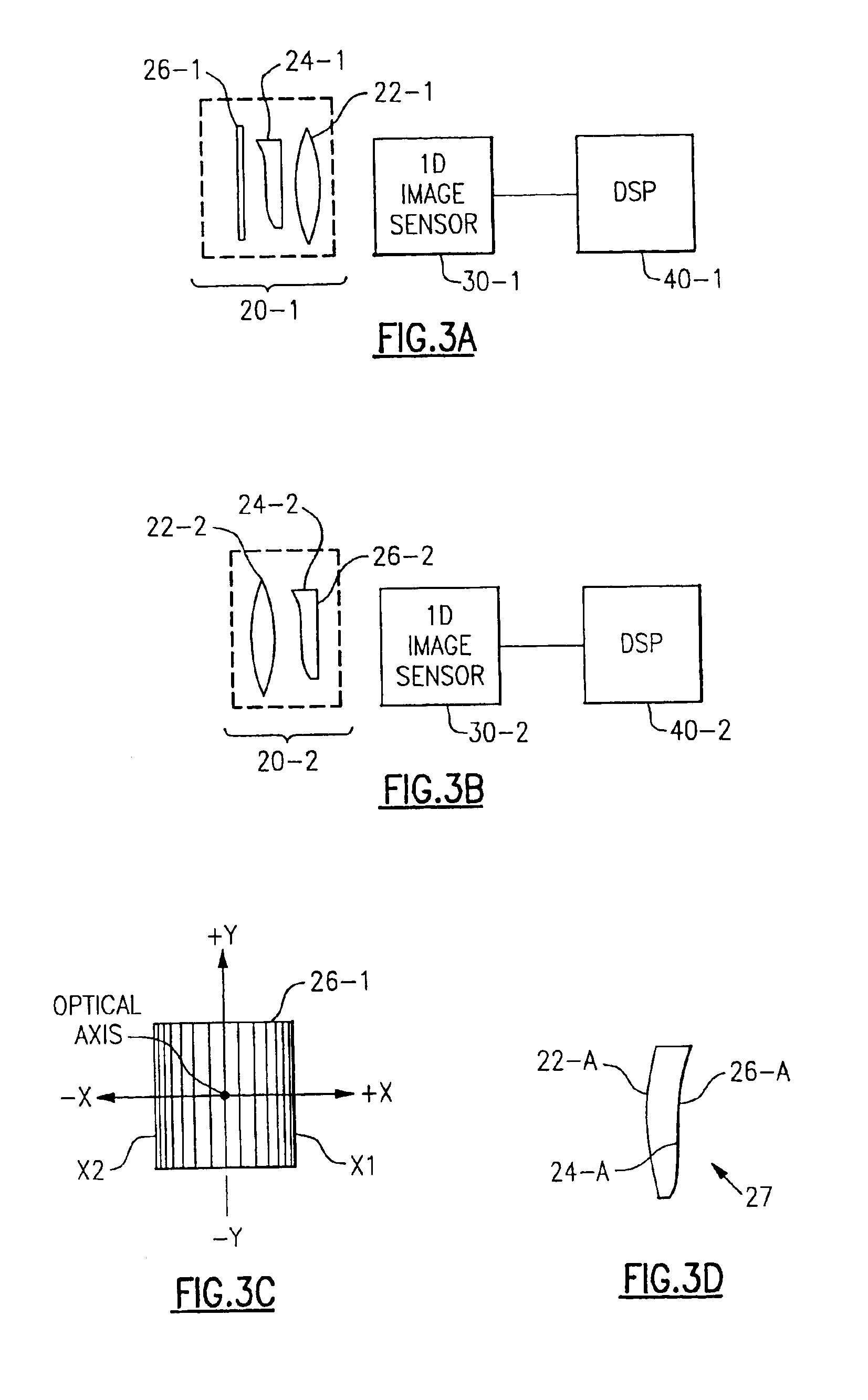
[0067]Referring to FIG. 3A there is shown a side view of a 1D imaging system constructed in accordance with the invention. This imaging system includes a 1D optical assembly 20-1, a 1D image sensor 30-1, and a DSP 40-1 which is adapted to implement a 1D version of the recovery function of the invention. In the embodiment of FIG. 3A optical assembly 20-1 includes a lens 22-1, a 1D phase mask 24-1 (the curvature of which is greatly exaggerated to clearly show its shape), and a stand alone 1D amplitude mask 26-1. In the preferred embodiment, 1D amplitude mask 26-1 is rectangular in form. As shown in FIG. 3C, the transmittance of mask 26-1 decreases smoothly and continuously as a function of the distance from the center line of the amplitude mask, along the X-axis until it reaches or approximates a value of zero at the X boundaries X1 and X2 thereof. This center line is located on the optical axis of optical assembly 20-1. This optical axis is perpendicular to the plane the object shown...

second embodiment

[0075]Referring to FIG. 3B there is shown a 1D imaging system constructed in accordance with the invention. The embodiment of FIG. 3B differs from that of FIG. 3A primarily in that its phase mask 24-2 is located at the rear rather than the front principal plane of its lens 22-2. In addition, the amplitude mask 26-2 of the imaging system of FIG. 3B takes the form of a film deposited on the rear surface of phase mask 24-2. Because the statements made in connection with the embodiment of FIG. 3A are equally applicable to the embodiment of FIG. 3B, the embodiment of FIG. 3B will not be discussed in detail herein.

[0076]As appreciated by those skilled in the art, it is the 1D character of image sensor 30-1 or 30-2 that is responsible for the fact that the imaging systems of FIGS. 3A and 3B are termed 1D imaging systems. As a result, in spite of the fact that the imaging systems of FIGS. 3A and 3B are 1D imaging systems, optical assemblies 20-1 and 20-2 may be constructed using either 1D o...


PUM


Abstract

Briefly stated, the operating depth of field for a bar code scanner, preferably a laser scanner, is increased by placing a cubic phase mask (CPM) in the scanning beam. The masked beam is then scanned and reflected off a bar code and received by a photodetector. The received signal is then processed to recover the original unperturbed representation of the bar code pattern. The processed signal has an increased depth of field over an unmasked scanner signal.

Description

CROSS-REFERENCE TO RELATED APPLICATIONS[0001]This application is a continuation of U.S. patent application Ser. No. 09 / 594,870 filed on Jun. 15, 2000 now U.S. Pat. No. 6,547,139, which is a continuation-in-part of U.S. patent application Ser. No. 09 / 113,523 filed on Jul. 10, 1998, now U.S. Pat. No. 6,097,856, issued Aug. 1, 2000, and entitled APPARATUS AND METHOD FOR REDUCING IMAGING ERRORS IN IMAGING SYSTEMS HAVING AN EXTENDED DEPTH OF FIELD. The priorities of the above applications are hereby claimed under 35 U.S.C. 120, and the above applications are hereby incorporated by reference herein in their entireties.FIELD OF THE INVENTION[0002]This invention pertains to the field of bar code scanners, and in particular to extending the depth of field for a laser bar code scanner.BACKGROUND OF THE INVENTION[0003]Many industries, including the assembly processing, grocery and food processing industries, utilize an identification system in which the products are marked with a bar code symb...

Claims


Application Information

Patent Timeline
IPC IPC(8): G02B27/00G06T5/00H04N1/409
CPCG02B27/0075H04N1/4092G06T5/003G06T2207/20192G06T5/73
Inventor HAVENS, WILLIAM H.HAMMOND, CHARLES M.
Owner HAND HELD PRODS
Learn More