Asymmetric error correction apparatus and method, and clock recovering apparatus for optical reading system employing the same

a clock recovery and optical reading technology, applied in the direction of restoring means or bias distortion, digital signal error detection/correction, baseband system details, etc., can solve the problem of reproducing data to be distorted, asymmetric phenomenon of rf signal, and difficult detection and correction of frequency error and phase error generated between recorded data and read data, etc. problem, to achieve the effect of reducing the time required for recovering asymmetric errors, accurate correction, and convenient clock recovery

Inactive Publication Date: 2005-11-08
SAMSUNG ELECTRONICS CO LTD
View PDF1 Cites 3 Cited by
  • Summary
  • Abstract
  • Description
  • Claims
  • Application Information

AI Technical Summary

Benefits of technology

[0031]According to the clock recovering apparatus provided with the asymmetric error correction apparatus, it has the advantage that the time required for recovering the asymmetric error is shortened, and an accurate correction is possible, enabling easy clock recovery. Also, according to the data recovering apparatus provided with the asymmetric error correction apparatus, it has the advantage that quick data recovery can be achieved.

Problems solved by technology

However, if data is recorded with an inaccurate pit length during a signal recording process, an asymmetric phenomenon of an RF signal is presented.
The ISI makes it difficult to detect and correct a frequency error and phase error generated between the recorded data and read data.
This causes the reproduced data to be distorted.
However, since the average value of two samples should be obtained for each sample, the conventional apparatus has the disadvantage of slow correction speed as shown in FIG. 12.
However, since it uses three samples neighboring the zero-crossing point, it has the disadvantage that it is difficult to accurately judge the polarity of the asymmetric signal in case that the environment of the optical channels is inferior.
Accordingly, the amount of jitter in a normal state becomes larger during the error tracking in the correction process as shown in FIGS. 14 and 15, and thus it has the disadvantage that it is difficult to achieve a stable operation of the following PLL loop.

Method used


Image

  • Asymmetric error correction apparatus and method, and clock recovering apparatus for optical reading system employing the same
  • Asymmetric error correction apparatus and method, and clock recovering apparatus for optical reading system employing the same
  • Asymmetric error correction apparatus and method, and clock recovering apparatus for optical reading system employing the same

Examples


Embodiment Construction

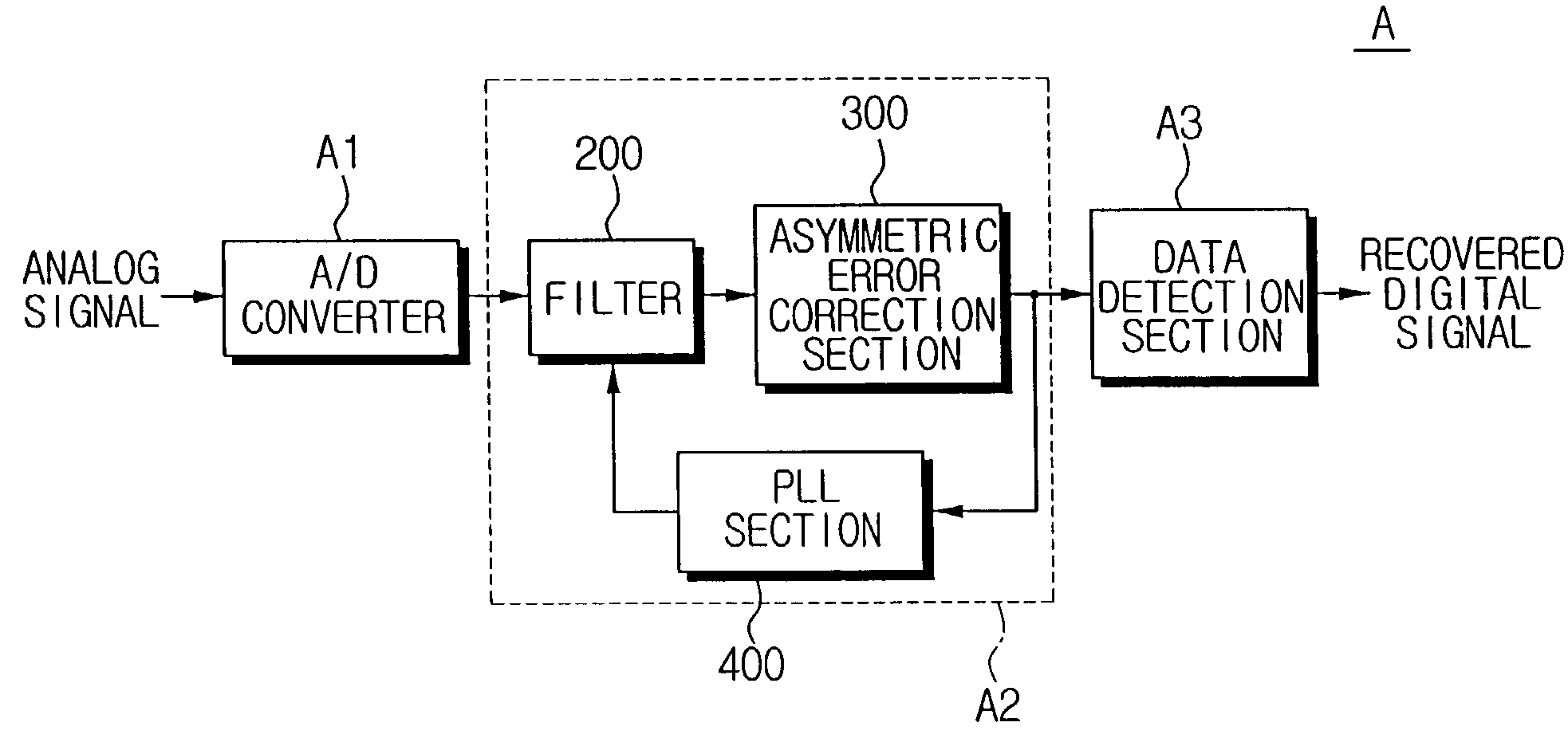
[0050]A data recovering apparatus A for an optical reading system for reading an analog signal from an optical recording medium of the present invention will now be described in detail with reference to FIG. 4.

[0051]Referring to FIG. 4, the data recovering apparatus A for an optical reading system includes an A / D converter A1, a clock recovering section A2, and a data detection section A3.

[0052]The A / D converter A1 converts the analog signal sequentially inputted into a digital signal Si. The clock recovering section S2 sequentially extracts four samples from samples of the digital signal Si inputted from the A / D converter A1. FIG. 8 illustrates the four samples D1k, D2k, D3k, D4k, or D1k-1, D2k-1, D3k-1, D4k-1 including a zero-crossing point tk or tk-1 extracted by the clock recovering section A2.

[0053]The clock recovering section A2 corrects the asymmetric error of the digital signal Si on the basis of the sum of the two side samples D1k and D4k, or D1k-1 and D4k-1 among the four ...


PUM

PropertyMeasurementUnit
polarityaaaaaaaaaa
asymmetric polarityaaaaaaaaaa
asymmetric polaritiesaaaaaaaaaa

Abstract

An asymmetric error correction apparatus and method, and clock recovering apparatus and data recovering apparatus for a system for reading data from an optical recording medium such as a CD or DVD that has a multi-level input signal and irregular characteristic of zero-crossing transition. The signal inputted from the optical recording medium is digitized, and a zero-crossing detector extracts four sequential samples and detects a zero-crossing point from the two intermediate samples. An asymmetric error detector judges an asymmetric state and asymmetric polarity of the digital signal from a sum of the two side samples among the four samples if the zero-crossing point is detected. A correction section accumulates the judged asymmetric polarities, judges an asymmetric error of the digital signal if the accumulated value exceeds a predetermined threshold, and corrects the asymmetric error of the read signal caused by an inaccurate pit length.

Description

BACKGROUND OF THE INVENTION[0001]1. Field of the Invention[0002]The present invention relates to an asymmetric error correction apparatus and method, and clock recovering apparatus and data recovering apparatus for an optical reading system employing the error correction apparatus. In particular, the present invention relates to an asymmetric error correction apparatus and method, and clock recovering apparatus and data recovering apparatus for an optical reading system employing the same that can correct distortion of a radio frequency (RF) signal caused by interference among data due to inaccurate pit and land lengths during data writing on an optical recording medium. The present application is based on Korean Application No. 2001-48227, filed Aug. 10, 2001, which is incorporated herein by reference.[0003]2. Description of the Related Art[0004]An optical recording system forms a pit corresponding to a signal to be recorded on an optical reading medium such as a compact disc (CD) ...

Claims


Application Information

Patent Timeline
Patent Type & Authority Patents(United States)
IPC IPC(8): G11B20/18G11B20/10H04L7/033H04L25/06
CPCG11B20/10037G11B20/10203G11B20/10222H04L7/0334H04L25/069G11B20/18
Inventor LEE, JUNG-HYUNKO, SEOK-JUNKIM, PAN-SOOCHOI, HYUNG-JIN
Owner SAMSUNG ELECTRONICS CO LTD
Why Eureka
Try Eureka