
Base station identification in orthogonal frequency division multiplexing based spread spectrum multiple access systems

a technology of spread spectrum multiple access and base station identification, applied in the field of wireless communication systems, can solve the problems of large probability of delay in identifying the base station transmitting the strongest signal, training symbols transmitted from different base stations would interfere with each other, and continue to interfere, etc., to achieve the effect of inherent latency

Inactive Publication Date: 2005-11-01
QUALCOMM INC
View PDF8 Cites 205 Cited by
  • Summary
  • Abstract
  • Description
  • Claims
  • Application Information

AI Technical Summary

Benefits of technology

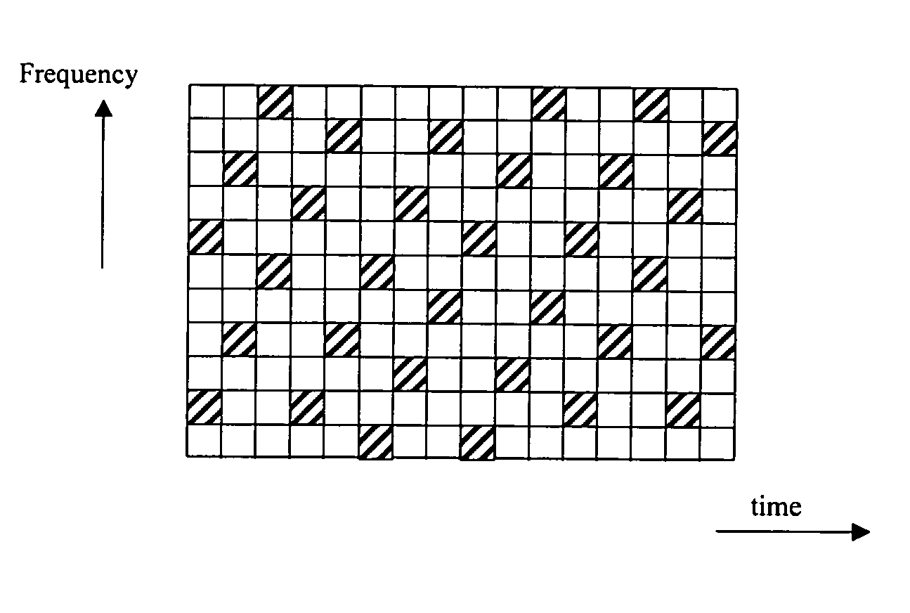
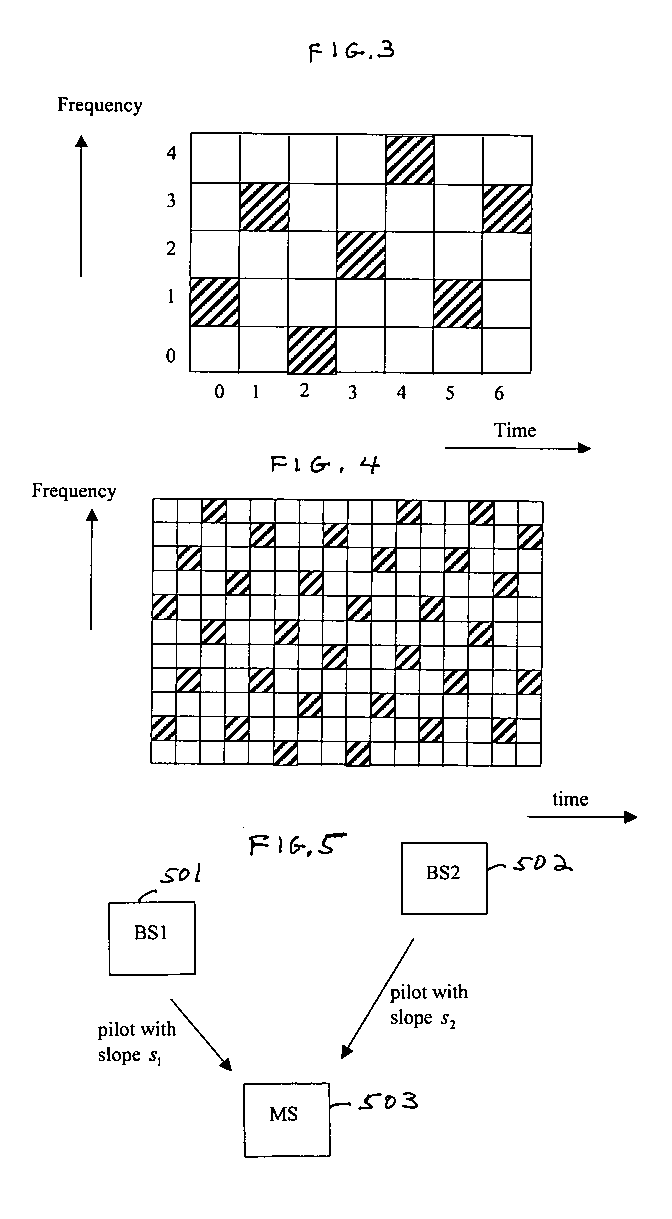
The patent text describes a method for identifying the strongest base station in a mobile communication system using a pilot tone hopping sequence. The pilot tone hopping sequence is based on a Latin Squares sequence, which allows the mobile user unit to easily locate the frequency of the pilot tones. The unique slope of the pilot tone hopping sequence is determined and used to identify the base station with the strongest downlink signal. This method does not require a training sequence, reducing latency.

Problems solved by technology

In such arrangements, there is a large probability that delays occur in identifying the base station transmitting the strongest signal because the training symbols are typically transmitted at the beginning of a frame.
It is also likely that the training symbols transmitted from different base stations would interfere with each other.
Indeed, it is known that once the training symbols interfere with each other they will continue to interfere.
Thus, if the training symbols are corrupted, then the data is also corrupted, thereby causing loss in efficiency.

Method used


Image

  • Base station identification in orthogonal frequency division multiplexing based spread spectrum multiple access systems
  • Base station identification in orthogonal frequency division multiplexing based spread spectrum multiple access systems
  • Base station identification in orthogonal frequency division multiplexing based spread spectrum multiple access systems

Examples


Embodiment Construction

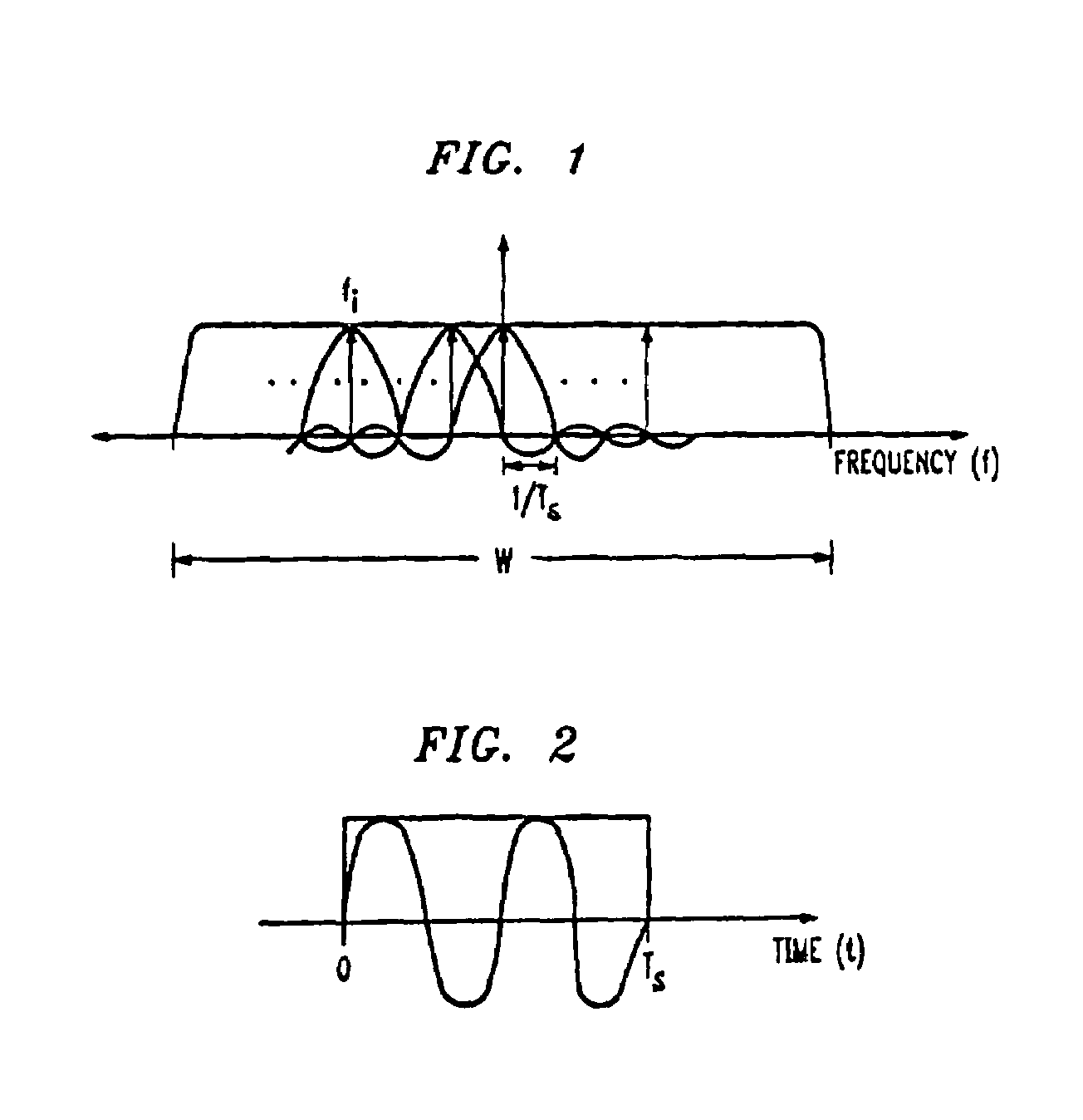
[0019]FIG. 1 illustrates a frequency domain representation in which a prescribed plurality of tones is generated in a prescribed bandwidth. In this example, bandwidth W is employed to generate a total of N tones, i.e., i=1, . . . , N. The tones are spaced at Δƒ=1 / TS apart, where Ts is the duration of an OFDM symbol. Note that the tones employed in this embodiment of the invention are generated differently than those generated for a narrow band system. Specifically, in a narrow band system the energy from each tone is strictly confined to a narrow bandwidth centered around the tone frequency, whereas in an Orthogonal Frequency Division Multiplexing (OFDM) system that is a wide band system the energy at a particular tone is allowed to leak into the entire bandwidth W, but it is so arranged that the tones do not interfere with one another.

[0020]FIG. 2 illustrates a time domain representation of tone ƒi within symbol interval Ts. Again, note that within each symbol interval Ts, data may...


PUM


Abstract

A base station having the strongest downlink signal is identified by utilizing a unique slope of a pilot tone hopping sequence being transmitted by a base station. Specifically, base station identification is realized by determining the slope of the strongest received pilot signal, i.e., the received pilot signal having the maximum energy. In an embodiment of the invention, the pilot tone hopping sequence is based on a Latin Squares sequence. With a Latin Squares based pilot tone hopping sequence, all a mobile user unit needs is to locate the frequency of the pilot tones at one time because the pilot tone locations at subsequent times can be determined from the slope of the Latin Squares pilot tone hopping sequence. The slope and initial frequency shift of the pilot tone hopping sequence with the strongest received power is determined by employing a unique maximum energy detector.

Description

RELATED APPLICATION[0001]This application is related U.S. patent application Ser. No. 09 / 551,791 which was filed on Apr. 18, 2000.TECHNICAL FIELD[0002]This invention relates to wireless communications systems and, more particularly, to orthogonal frequency division multiplexing (OFDM) based spread spectrum multiple access (SSMA) systems.BACKGROUND OF THE INVENTION[0003]It is important that wireless communications systems be such as to maximize the number of users that can be adequately served and to maximize data transmission rates, if data services are provided. Wireless communications systems are typically shared media systems, i.e., there is a fixed available bandwidth that is shared by all users of the wireless system. Such wireless communications systems are often implemented as so-called “cellular” communications systems, in which the territory being covered is divided into separate cells, and each cell is served by a base station.[0004]In such systems, it is important that mo...

Claims


Application Information

Patent Timeline
Patent Type & Authority Patents(United States)
IPC IPC(8): H04L27/26H04L5/02H04B1/69H04B1/713H04B1/7143H04B1/7156H04B7/26H04J11/00
CPCH04B1/7143H04B1/7156H04L5/0019H04L5/0048H04L27/2613H04L27/2657H04L27/2675H04B2001/71563H04L25/0226H04B1/713
Inventor LAROIA, RAJIVLI, JUNYIRANGAN, SUNDEEPVISWANATH, PRAMOD
Owner QUALCOMM INC
Learn More