
Phase-error-compensation techniques in a fractional-N PLL frequency synthesizer

a fractional-n pll frequency synthesizer and phase error compensation technology, applied in the field of fractional-dividefactor phaselocked loops, can solve the problems of high power consumption of such a dac, difficult design and implementation of multi-bit dacs with such a high level of resolution, etc., and achieve the effect of reducing the resolution requirements and not too costly

Active Publication Date: 2005-11-01
ST ERICSSON SA
View PDF8 Cites 27 Cited by
  • Summary
  • Abstract
  • Description
  • Claims
  • Application Information

AI Technical Summary

Benefits of technology

[0014]In particular, an embodiment of the present invention reduces the resolution requirements in the generation of the phase-error compensation signal, so as to make the implementation of phase-error compensation techniques practical and not too costly.

Problems solved by technology

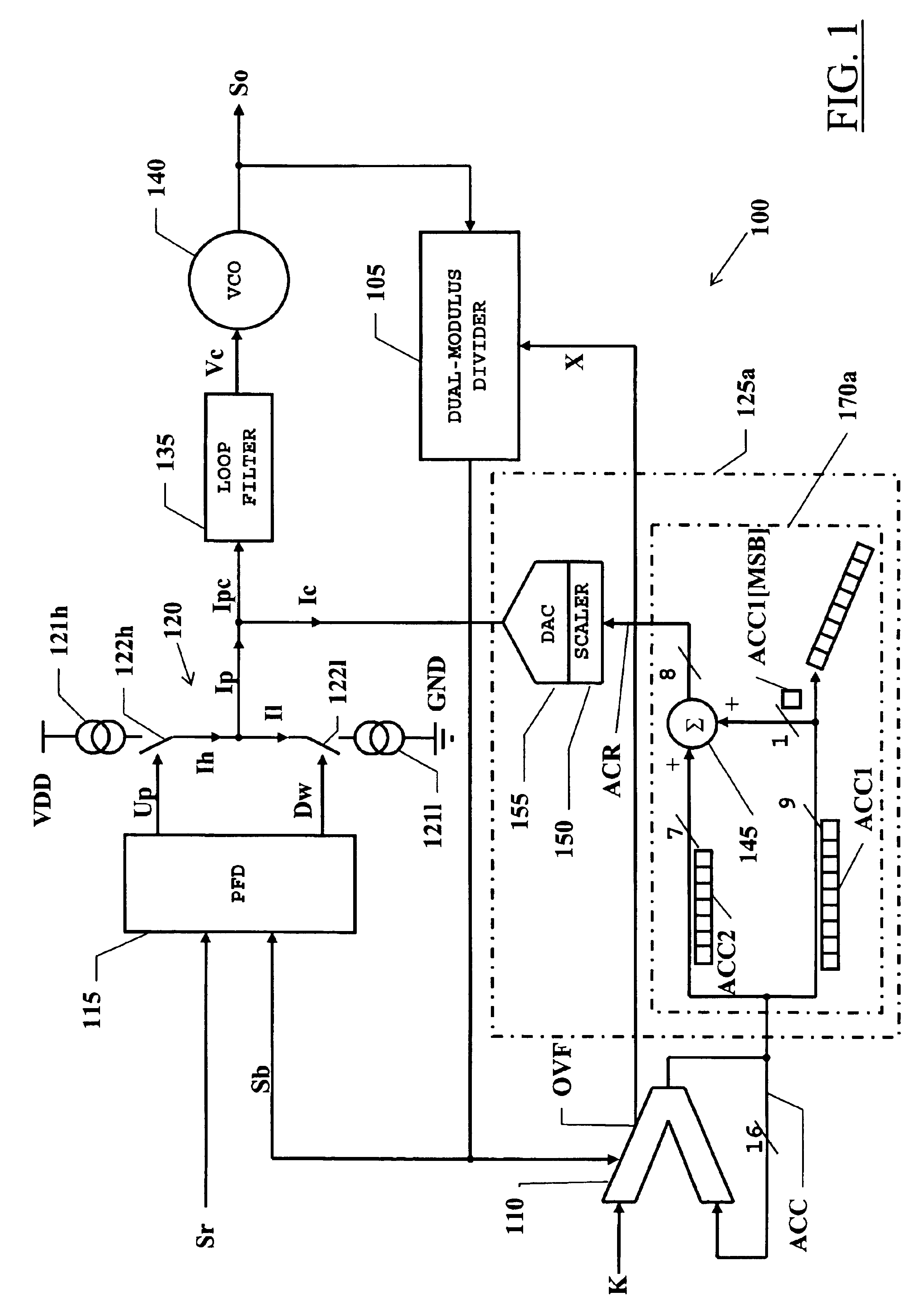
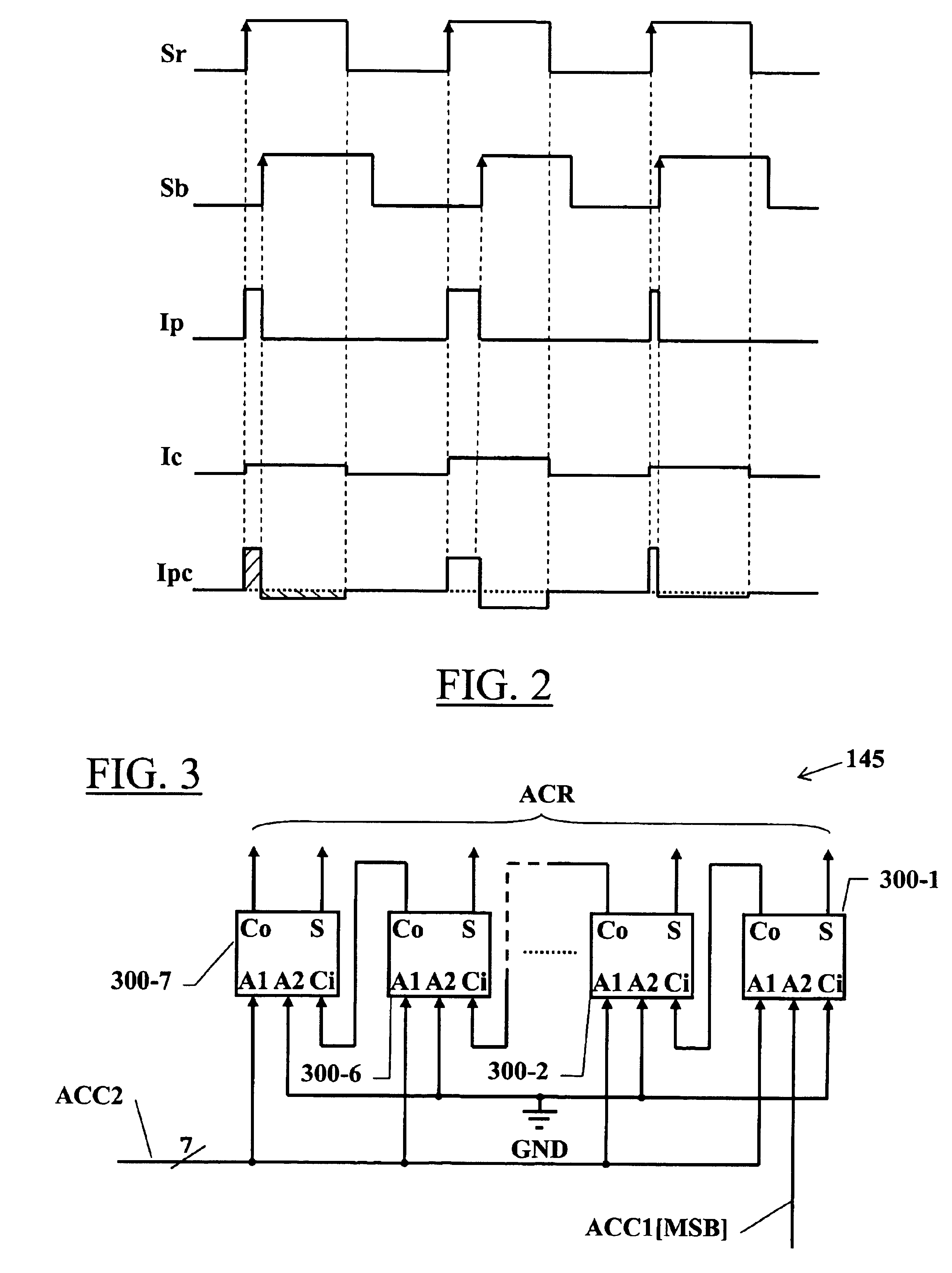
A problem of fractional-N PLLs is that the feedback signal and the reference signal, even in the locked condition, are not instantaneously at the same frequency, but only so on average; the frequency difference between the two signals translates into a phase error having a value that varies with the same periodicity as the variation of the frequency-divider divide factor.
A problem of the above-mentioned phase-error compensation technique relates to the resolution required for the DAC generating the compensation current.
Designing and implementing a multibit DAC with such a high level of resolution is a challenging and almost impractical task; just to cite one problem, the power consumption of such a DAC would be very high.

Method used


Image

  • Phase-error-compensation techniques in a fractional-N PLL frequency synthesizer
  • Phase-error-compensation techniques in a fractional-N PLL frequency synthesizer
  • Phase-error-compensation techniques in a fractional-N PLL frequency synthesizer

Examples


example a

[0057]

MSB ←------→ LSBACC0110101001010010ACC1001010010ACC20110101ACR00110101

example b

[0058]

MSB ←------→ LSBACC0110101101010010ACC1101010010ACC20110101ACR00110110

example c

[0059]

MSB ←------→ LSBACC1111111101010010ACC1101010010ACC211111111ACR100000000

[0060]Alternatively, elementary adders without a carry-in input may be used, whereby the carry-out output of the previous adder is fed to one of the two addend inputs of the next adder.

[0061]The rounded accumulator value is fed to a scaler 150 and then to a multi-bit DAC 155 capable of converting a digital code of (m−n)+1 bits. The DAC 155 converts the rounded accumulator value ACR, i.e., the rounded phase error, into a phase-error-compensation current Ic, which is applied to the output node of the charge pump 120.

[0062]It has been found that rounding the phase-error value provided by the accumulator 110 allows reducing the resolution of the DAC used for generating the phase-error-compensation current; at the same time, the low-frequency spurs that are inevitably generated as a consequence of the rounding have an energy level lower (approximately a factor of two) than that of the low-frequency spurs that w...


PUM


Abstract

A fractional-type phase-locked loop circuit, for synthesizing an output signal multiplying a frequency of a reference signal by a selected fractional conversion factor, includes a frequency divider for generating a feedback signal dividing the frequency of the output signal by a frequency division factor selectable among at least two different integer-value division factors, and frequency divider control means for causing the frequency division factor to vary between the at least two integer-value division factors in a pre-defined number of cycles, thereby an average frequency division factor over said pre-defined number of cycles has a fractional value. Means are provided for compensating a phase error introduced by the frequency divider on the basis of a value indicative of the phase error obtained from said frequency divider control means. The phase-error compensation means includes rounding means, receiving an input binary code with a first number of binary digits, indicative of the phase error value, and providing an output binary code, with a second number of binary digits lower than the first number of digits, defining a rounded phase error value.

Description

PRIORITY CLAIM[0001]This application claims priority from European patent application No. 03425155.3, filed Mar. 14, 2003, which is incorporated herein by reference.TECHNICAL FIELD[0002]An embodiment of the present invention relates generally to frequency synthesizers, and particularly to fractional-divide-factor Phase-Locked Loops (commonly referred to as fractional-N PLLs). Specifically, an embodiment of the invention concerns techniques for compensating phase errors in fractional PLLs.BACKGROUND[0003]PLLs are commonly used in (indirect) frequency synthesis applications. A PLL consists of a negative feedback circuit that allows multiplying the frequency of a reference signal by a selected frequency conversion factor; this results in the generation of a tuneable and stable output signal at the desired frequency.[0004]For this purpose, a frequency divider scales the frequency of the output signal by the conversion factor. The resulting frequency-scaled signal is fed back to a phase ...

Claims


Application Information

Patent Timeline
IPC IPC(8): H03L7/197H03L7/16
CPCH03L7/1976
Inventor ALBASINI, GUIDO GABRIELEMILANI, ENRICO TEMPORITI
Owner ST ERICSSON SA
Learn More