
Detector for a bipolar time-of-flight mass spectrometer

Inactive Publication Date: 2005-10-25
PHOTONIS SCI INC
View PDF22 Cites 31 Cited by
  • Summary
  • Abstract
  • Description
  • Claims
  • Application Information

AI Technical Summary

Benefits of technology

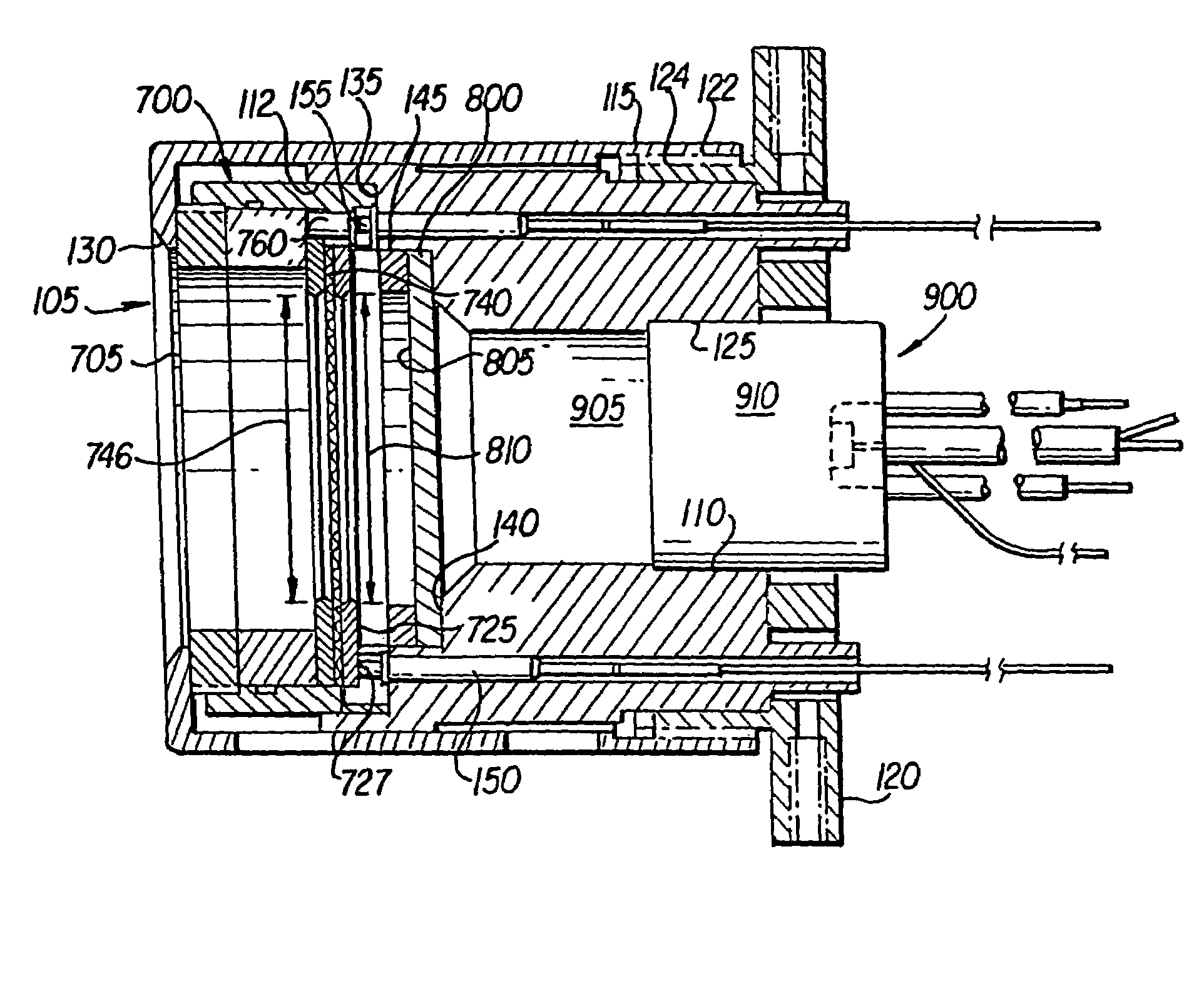
[0027]The invention overcomes the problems discussed above with a replaceable, electronically-isolated, MCP-based spectrometer detector cartridge with enhanced sensitivity.
[0028]The invention eliminates the potential for destruction of expensive spectrometry equipment from high-voltage power surges due to current source, vacuum or other failures by electro-optically isolating the charge collector from the high post-acceleration potential across the detector assembly.
[0029]The invention improves the uptime of a TOF mass spectrometry device by providing an easily replaceable, electro-optically isolated MCP cartridge.
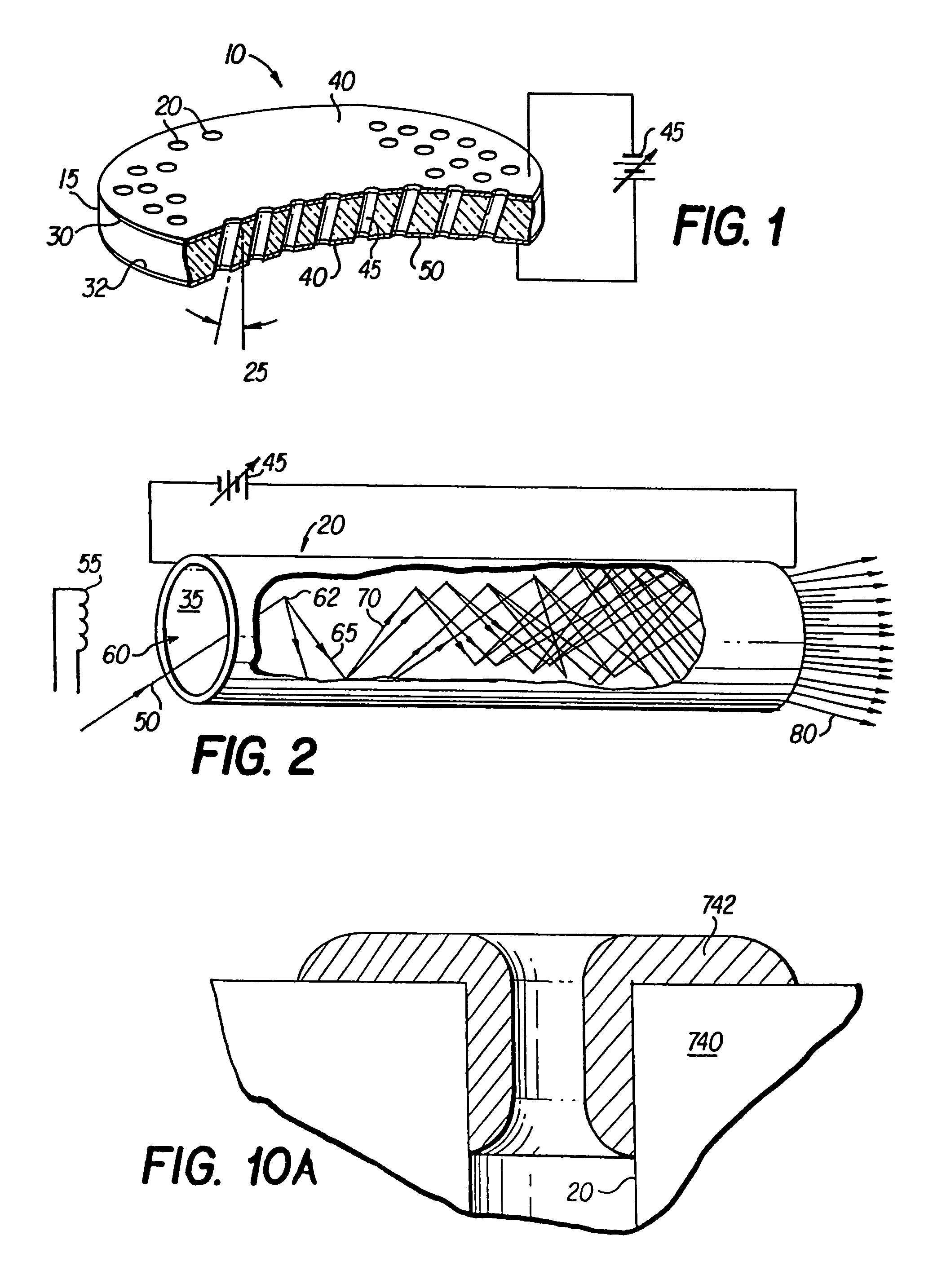
[0030]The invention improves the sensitivity of an MCP-based spectroscope by providing a coating on the MCP that enhances the secondary electron emissivity characteristics of the MCP selected from magnesium oxide (MgO), tin oxide (SnO2), quartz (SiO2), barium fluoride (BaF2), rubidium tin (Rb3Sn), beryllium oxide (BeO), diamond and combinations thereof.

Problems solved by technology

SCEM's typically are not used in modern TOFMS instruments because SCEM's provide limited dynamic range and temporal resolution, in the order of 20–30 nanoseconds to full width at half maximum (ns FWHM).
However, MCP's cannot withstand excessive voltages there across without risk of significant degradation.
Unfortunately, this creates great potential for arcing or short circuiting between the output and the anode, the energy from which could damage or destroy sensitive and expensive spectrometry equipment.
Thus, attaining superior temporal range with an MCP-based spectrometer which also has superior dynamic capabilities, or high sensitivity, may come at significant, unpredictable cost.
Another problem with MCP-based detectors is that, over time, MCP's wear and require replacement.
Some mass spectrometers are constructed in a manner that does not permit field replacement of the MCP.
This is undesirable in terms of cost and out-of-service time for the instrument.
However, the charge collector of the '858 cartridge is not electro-optically isolated from the high post acceleration potential of the MCP element therein, like the present cartridge.

Method used


Image

  • Detector for a bipolar time-of-flight mass spectrometer
  • Detector for a bipolar time-of-flight mass spectrometer
  • Detector for a bipolar time-of-flight mass spectrometer

Examples


Embodiment Construction

[0046]The invention is a replaceable, electronically-isolated, MCP-based spectrometer detector cartridge with enhanced sensitivity.

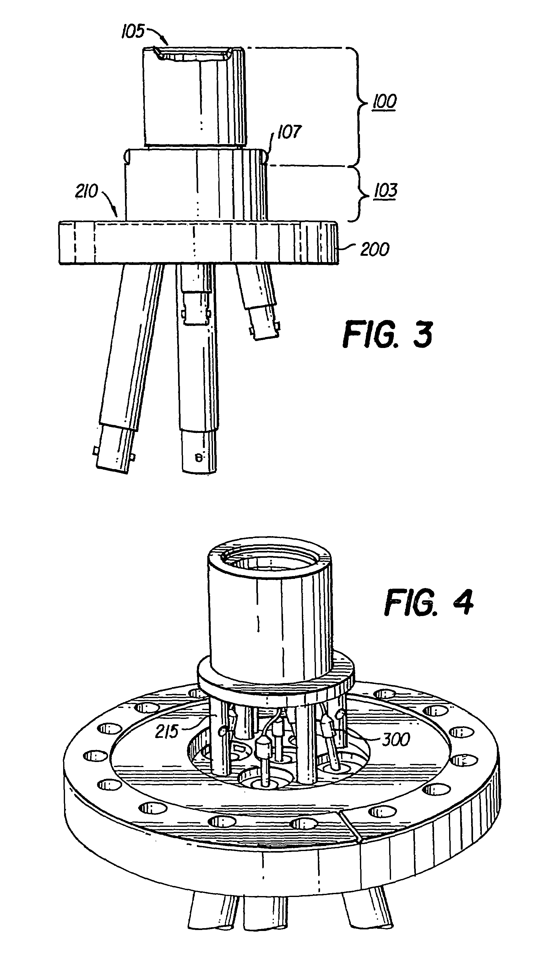
[0047]FIGS. 3 and 4 show a modular detector assembly 100 assembled with a modified vacuum flange 200 of a TOF spectrometer (not shown). FIG. 3 also shows a shield 103 interposed between detector assembly 100 and flange 200. An ionization source (not shown) directs charged or neutral particles, for example, electrons, ions and photons, toward an input end 105 of detector assembly 100.

[0048]Detector assembly 100 is adapted to be secured to a vacuum side 210 of vacuum flange 200 with a plurality of rods 215.

[0049]A plurality of connectors 300 pass through flange 200. Connectors 300 supply electrical energy to pogo pins (not shown) which contact elements (not shown) for creating electric fields in detector assembly 100 for accelerating particles therein, as discussed below.

[0050]Shield 103 is connected to detector assembly 100 with threaded fasteners 107. Sh...


PUM


Abstract

A replaceable, electronically-isolated, MCP-based spectrometer detector cartridge with enhanced sensitivity is disclosed. A mass detector is electro-optically isolated from a charge collector with an electron multiplier for converting a charged particle into a multiplicity of electrons and a scintillator for converting the multiplicity of electrons into a multiplicity of photons. A light sensor is provided to convert the multiplicity of photons back into electrons which are summed into a charge pulse. The light sensor is realized by any of a plurality of photo-responsive devices.

Description

CROSS REFERENCE TO RELATED APPLICATION[0001]This application is a continuation-in-part of U.S. Nonprovisional application Ser. No. 09 / 809,090, filed on Mar. 16, 2001, now U.S. Pat. No. 6,828,729 which claims the benefit of U.S. Provisional Application No. 60 / 189,894, filed Mar. 16, 2000.BACKGROUND OF THE INVENTION[0002]Conventional time-of-flight mass spectrometry (TOFMS) is a technique that uses electron impact (EI) ionization. EI ionization involves irradiating a gas phase molecule of the unknown composition with an electron beam, which displaces outer orbital electrons, thereby producing a net positive charge on the newly formed ion.[0003]TOFMS has seen a resurgence due to the commercial development of two new ionization methods: electrospray ionization (ESI) and matrix-assisted laser desorption / ionization (MALDI). The availability of low cost pulsed extraction electronics, high speed digital oscilloscopes and ultra-high speed microchannel plate detectors have improved the mass r...

Claims


Application Information

Patent Timeline
IPC IPC(8): H01J43/24H01J43/00G01T1/20G01T1/28G01T1/29G01N27/62H01J49/02H01J49/06H01J49/40
CPCH01J43/246H01J49/025H01J2237/24435
Inventor LAPRADE, BRUCESTARCHER, RONALD
Owner PHOTONIS SCI INC
Learn More