
Flashlight with light emitting diode source

Inactive Publication Date: 2005-10-25
GENERAL ELECTRIC CO
View PDF12 Cites 78 Cited by
  • Summary
  • Abstract
  • Description
  • Claims
  • Application Information

AI Technical Summary

Benefits of technology

[0010]One advantage of the present invention is the provision of a flashlight having longer life and increased reliability.
[0011]Another advantage of the present invention resides in a flashlight having a minimal number of components.
[0012]Another advantage of the present invention is provided by eliminating the need for a filament for flashlights, thereby eliminating the potential for filament failure.
[0013]Another advantage of the present invention is the ability to more precisely control the light emitted from the flashlight.
[0014]Another advantage of the present invention is the provision of a flashlight having a minimal cost of operation due to the inherently low power consumption of the device.
[0015]Yet another advantage of the present invention is the provision of a flashlight capable of operating at relatively cool temperatures.

Problems solved by technology

Filament lamps and cathode tubes, although widely used and commercially successful, are relatively fragile and require careful handling.
Components of these lamps often break, even when receiving only a small shock.
In addition, filament lamps have a relatively short operating life, thereby giving users the trouble of frequently replacing a burned out bulb and tube shaped portions.
Furthermore, filament lamps are not the most economical.
These lamps have numerous components making them relatively expensive to manufacture.
Finally, filament lamps have a relatively high power consumption.
However, the first commercially available white light LED systems were not competitive with standard light sources with respect to performance, since the phosphor layer only partially transformed the UV or blue light into longer wavelengths.
As already discussed, current incandescent lamps used for flashlights have multiple components (increasing the cost to manufacture), are fragile, and have a relatively short operating life.
To date, no device exists which adequately utilizes an LED system in flashlights.

Method used


Image

  • Flashlight with light emitting diode source
  • Flashlight with light emitting diode source
  • Flashlight with light emitting diode source

Examples


Embodiment Construction

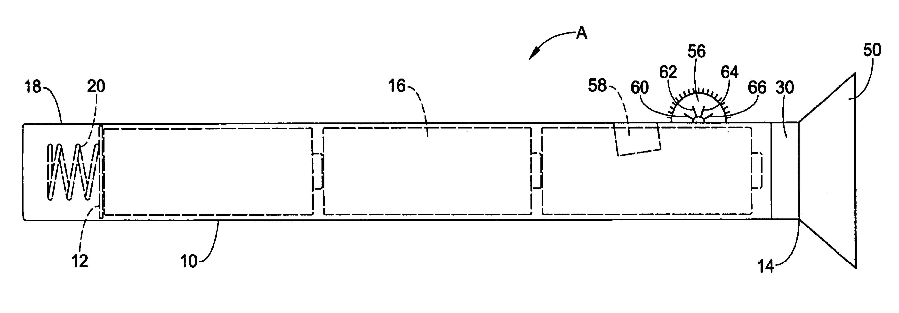
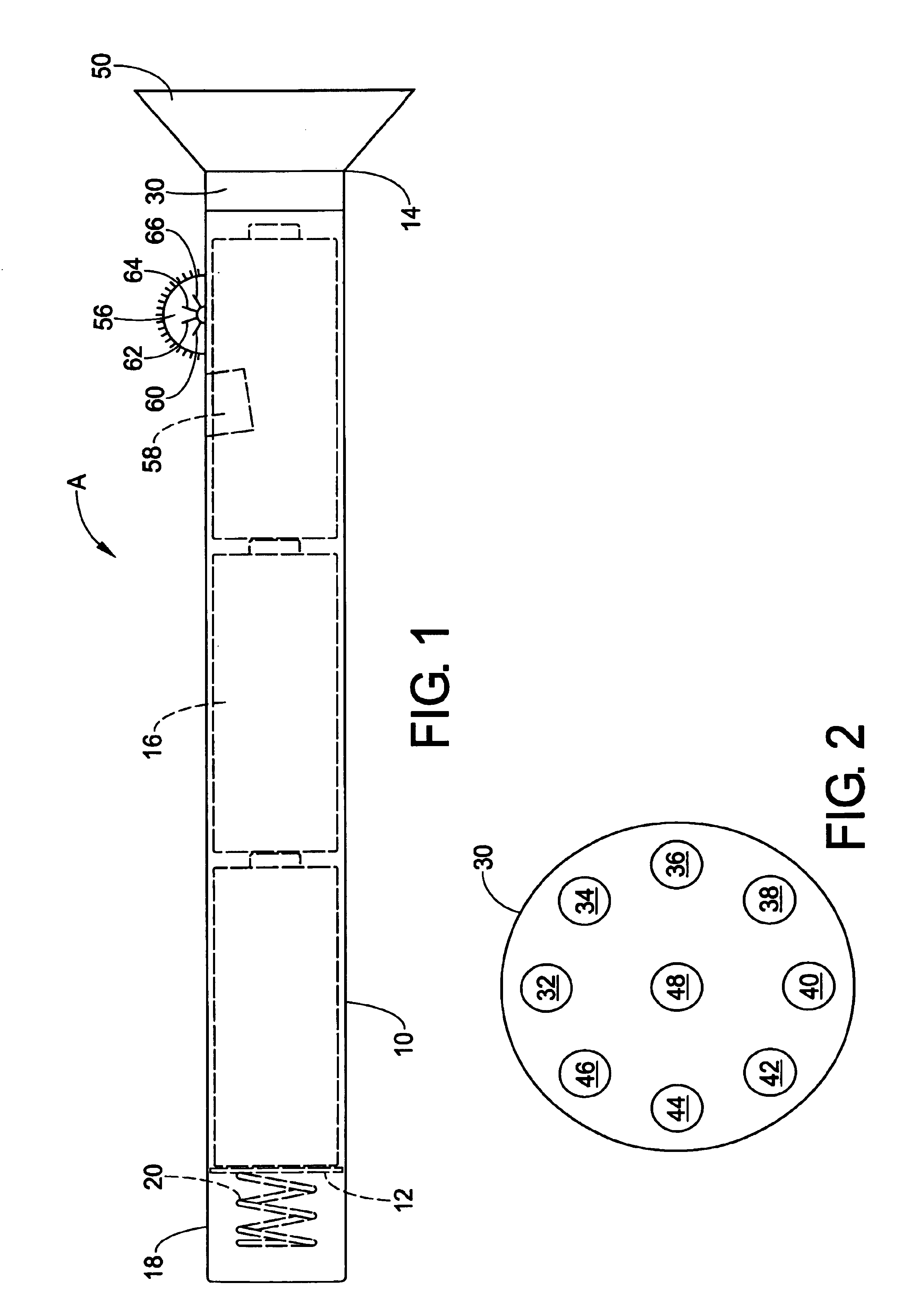
[0023]FIG. 1 shows an exemplary embodiment of a flashlight A in accordance with the present invention. The flashlight includes a housing 10 having a first end 12 and a second end 14. Although the housing is preferably a polymeric material and is shown as being substantially cylindrical, other materials or configurations (such as a pistol grip conformation) may be used without departing from the scope and intent of the present invention. A series of batteries 16 are enclosed within the housing and are disposed along a longitudinal axis of the housing. The batteries function as the power source for the flashlight and may be of any desired size and type, including but not limited to alkaline, nickel cadmium, standard, heavy duty, lithium, nickel metal hydride, and others. The power source can be a capacitor or other energy storage means due to the inherent high efficiency of the device.

[0024]A battery cap 18 defines a first end 12 of the housing and functions to secure the batteries in...


PUM


Abstract

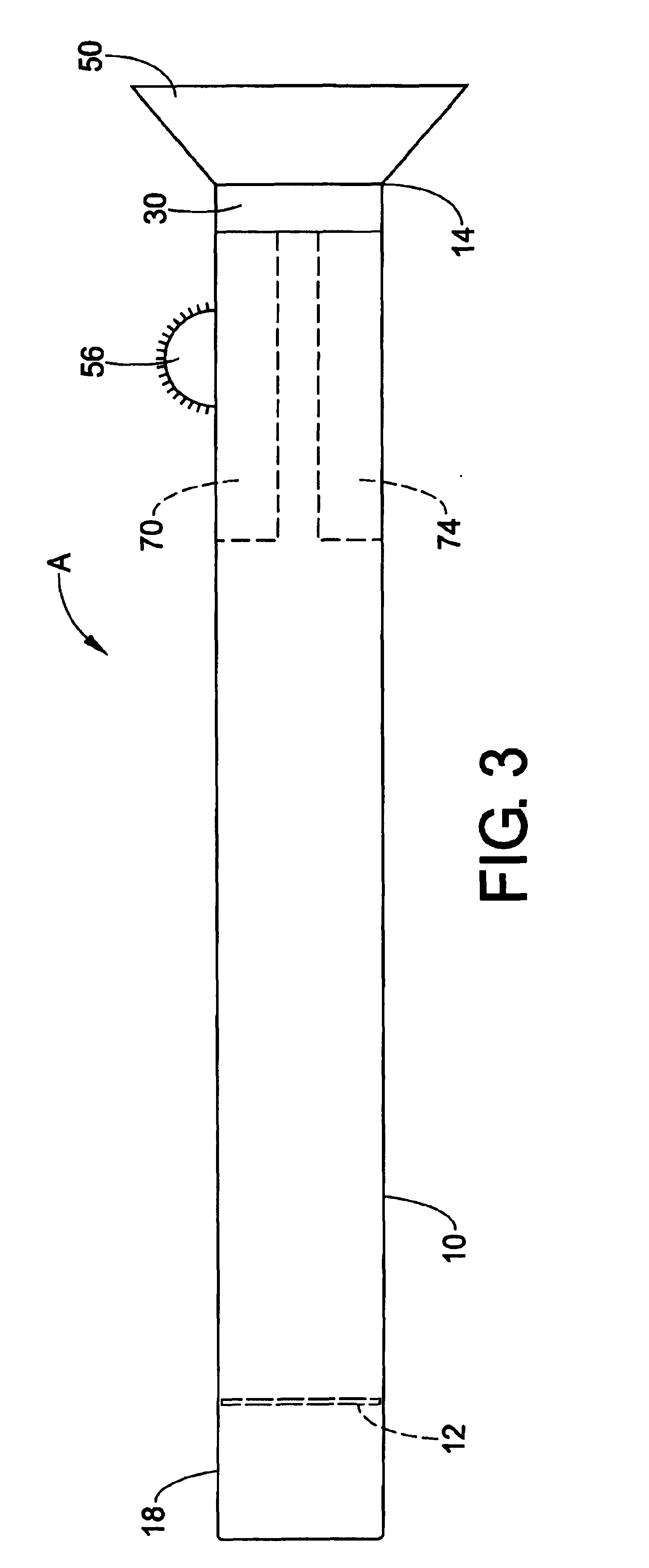
An apparatus for improving the performance of flashlights includes a substantially cylindrical housing (10) having a first end (12) and a second end (14). A battery cap (18) is operatively connected to the first end of the housing and functions to secure a series of batteries in place. A series (30) of light emitting diodes (LED) (32-48) are mounted within the flashlight housing at the end opposite the battery cap. The series of LEDs form an LED array which operates as the light source for the flashlight. A substantially cone-shaped optical assembly (50) extends outward from the second end of the housing and operates to focus and disperse the LED beam emitted by the LED array. The flashlight further includes an adjustable switch (56) disposed on the exterior of the housing. The switch is coupled to a variable resistor (58) which permits control over the light level and / or battery life. An electronic current regulator (70), enclosed by the housing, allows the LED beam to remain at a constant and desired light level, thereby increasing the efficiency of the battery life. A dynamic pulse control system (74) is coupled to the switch which takes advantage of the human eye perceiving the pulsed beam to be continuous. The pulse control also increases the peak current through the LED source.

Description

BACKGROUND OF THE INVENTION[0001]1. Field of the Invention[0002]This invention pertains to an apparatus for improving the performance of flashlights by providing a longer lighting life and higher efficacy. More particularly, the invention relates to improving flashlight performance by replacing a standard incandescent miniature lamp found in conventional flashlights with a light emitting diode (LED).[0003]2. Discussion of the Art[0004]Conventional flashlights use miniature incandescent lamps as a light source. Incandescent lamps generally require filaments and cathode tubes for operation. Filament lamps and cathode tubes, although widely used and commercially successful, are relatively fragile and require careful handling. Components of these lamps often break, even when receiving only a small shock. In addition, filament lamps have a relatively short operating life, thereby giving users the trouble of frequently replacing a burned out bulb and tube shaped portions. Furthermore, fil...

Claims


Application Information

Patent Timeline
IPC IPC(8): F21L4/00F21L4/02F21V14/02F21V14/04F21V23/04
CPCF21L4/027F21V14/025F21V14/045F21V23/0414F21Y2101/02F21Y2115/10
Inventor NELSON, WORDELLELGHOROURY, HESHAM MTHOMAS, EDWARD J.
Owner GENERAL ELECTRIC CO
Learn More