Eureka AIR delivers breakthrough ideas for toughest innovation challenges, trusted by R&D personnel around the world.

Radio communication system, radio base-station apparatus, mobile radio-station apparatus, radio zone assignment method, and radio communication method

Active Publication Date: 2005-10-18
SONY CORP
View PDF8 Cites 51 Cited by
  • Summary
  • Abstract
  • Description
  • Claims
  • Application Information

AI Technical Summary

Benefits of technology

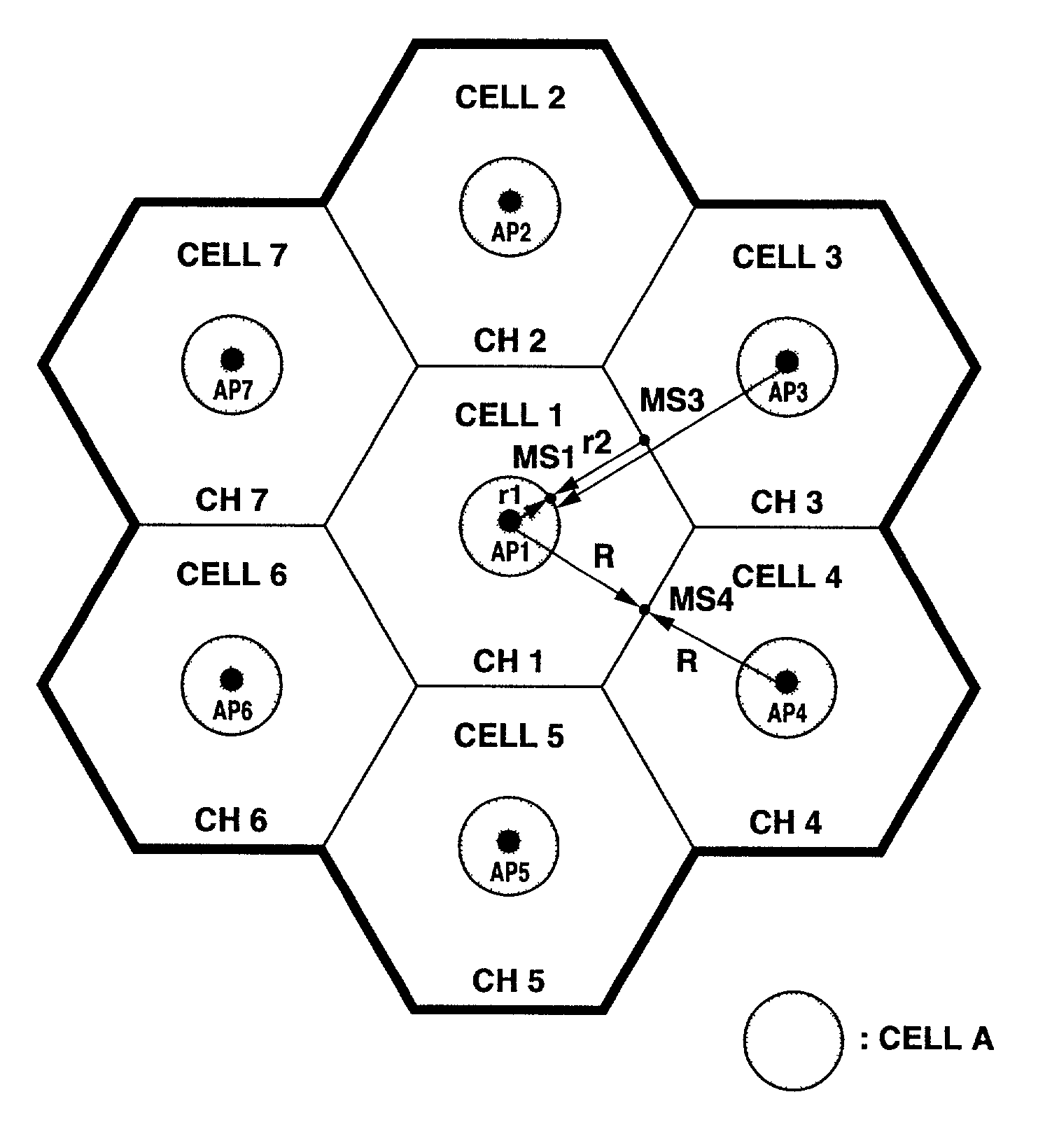
[0015]The present invention has been made in view of the foregoing. An object of the invention is to provide a radio communication system in which frequency division sets the channels, rendering the inter-station synchronization unnecessary, which can cover a larger geographical service area, and which can yet increase communication speed.
[0021]As described above, this invention can provide a radio communication system having a plurality of frequency channels, each assigned to one multi-carrier signal of OFDM scheme. In the system, the channels are simultaneously used in the center part of a cell, thereby transmitting data between the base station and any terminal at high speed. Therefore, the radio communication system can therefore help the user of the terminal to achieve Internet accesses at the highest speed possible.
[0022]With the present invention it is possible to expand the geographical area, without synchronizing the adjacent base stations.
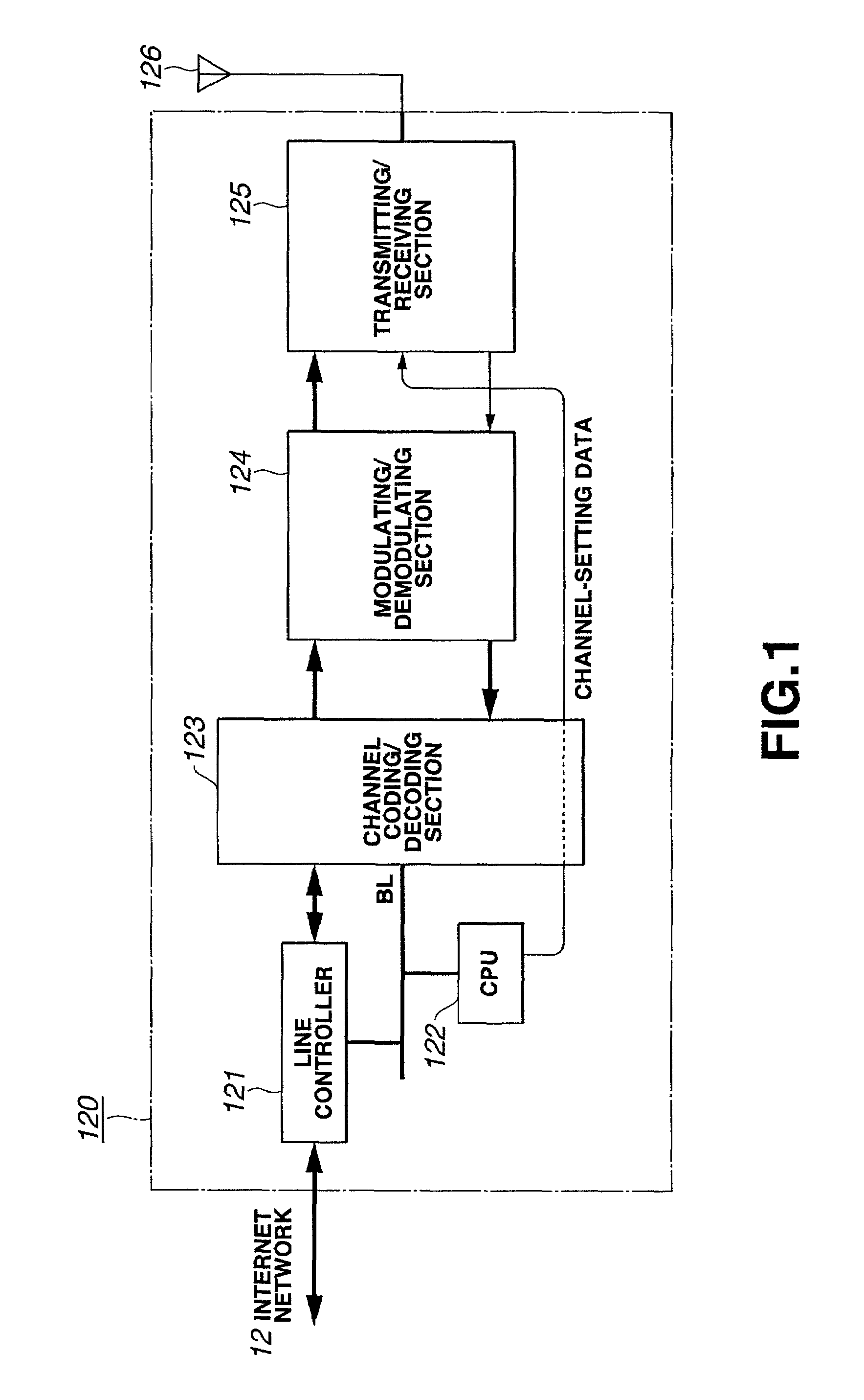
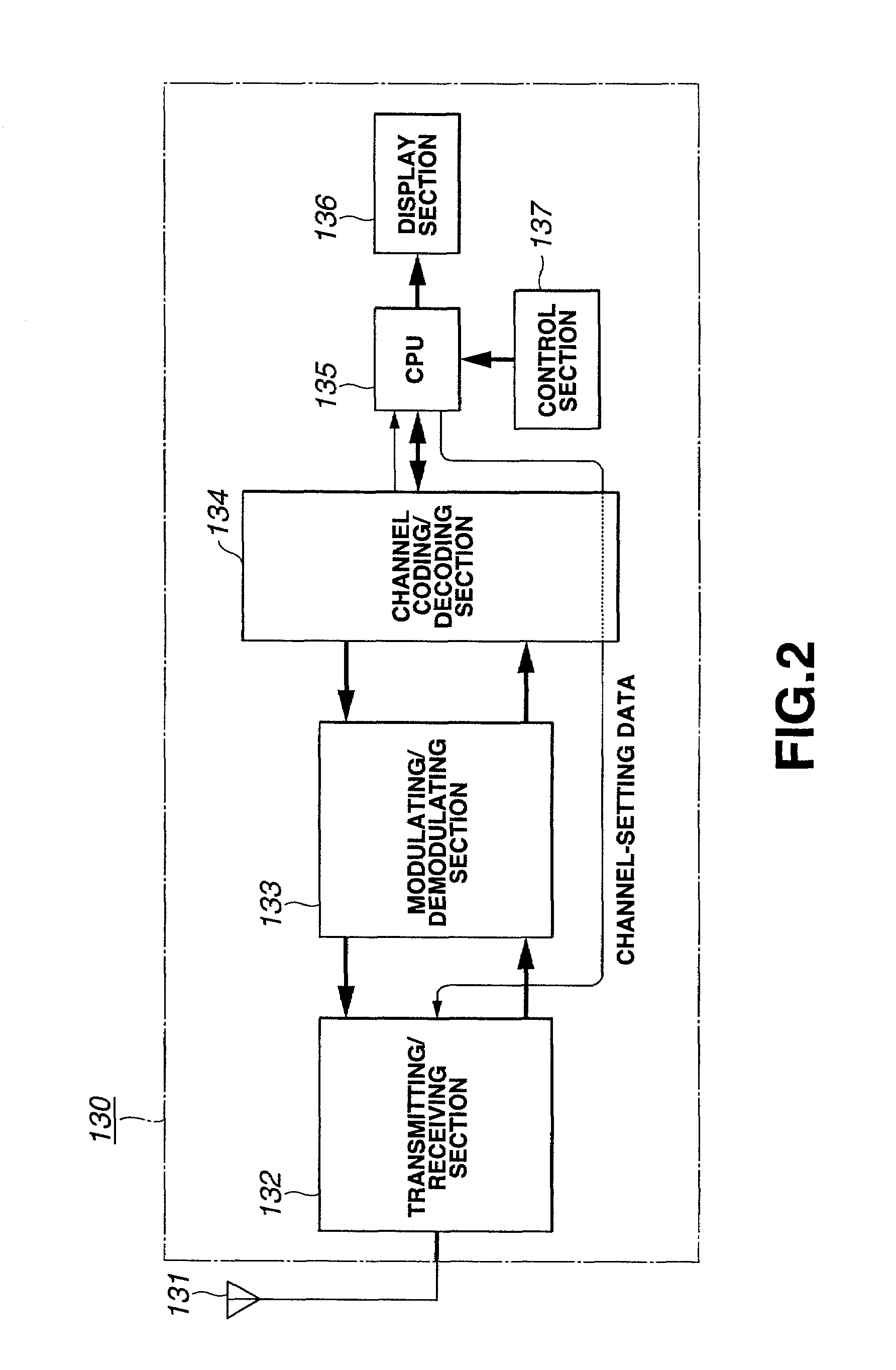
[0023]In the radio communication system of the invention, neither the base station nor the communication terminal needs to have two or more transmitting / receiving sections or two or more modulation / demodulation sections. The system can therefore be provided at a low hardware cost.

Problems solved by technology

A radio communication system that employs the time-division method is inevitably complex in configuration.
This makes it impossible to increase the transmission speed.

Method used


Image

  • Radio communication system, radio base-station apparatus, mobile radio-station apparatus, radio zone assignment method, and radio communication method
  • Radio communication system, radio base-station apparatus, mobile radio-station apparatus, radio zone assignment method, and radio communication method
  • Radio communication system, radio base-station apparatus, mobile radio-station apparatus, radio zone assignment method, and radio communication method

Examples


Embodiment Construction

[0039]Embodiments of the present invention will be described, with reference to the accompanying drawings.

[0040]The present invention may be applied to such a data communication system as is shown in FIG. 4.

[0041]As shown in FIG. 4, the data communication system comprises a content server 11, a base station 20 and a communication terminal 30. The content server 11 and the base station 20 are connected by the Internet network 12. The data communication system is designed to provide service called “IP (Internet Protocol) connection,” which connects the base station 20 to the content server 11.

[0042]The base station 20 performs transmission scheme such as QPSK modulation, thereby to accomplish radio communication with the communication terminal 30. Thus, the base station 20 relays data from the terminal 30 to the Internet network 12.

[0043]The communication system of the invention employs the multi-carrier radio transmission scheme, which will be described below.

[0044]With the communica...


PUM


Abstract

A plurality of frequency-channels are provided, each composed of an OFDM multi-carrier. The OFDM sub-carrier of each channel is orthogonal to the sub-carrier of any other channel, so that two or more channels may be considered to transmit the same OFDM signal. Further, a sub-area that uses two or more channels is provided in each service area in which a base station is located at the center and assigned with a basic-frequency channel.

Description

BACKGROUND OF THE INVENTION[0001]1. Field of the Invention[0002]The present invention relates to a radio communication system, a radio base-station apparatus, a mobile radio-station apparatus, a radio-zone assignment method and a radio communication method, all fit for use in mobile data communication, particularly radio transmission of multi-carrier signals.[0003]2. Related Art[0004]Two methods of setting many channels to provide mobile communication service in a larger geographical area are known. They are time division and frequency division. In the time-division method, use-time zones are assigned to cells, respectively, and the base stations must therefore be synchronized. A radio communication system that employs the time-division method is inevitably complex in configuration. In the frequency-division method, specific frequencies are assigned to the cells, respectively, and each base station can use the frequency assigned to it and can be controlled independently of any other...

Claims


Application Information

Patent Timeline
IPC IPC(8): H04L5/02H04Q7/36H04Q7/38H04J11/00H04W16/02H04W16/10H04W16/12H04W28/00H04W72/00H04W72/04
CPCH04L5/023H04W72/048H04W16/02H04W72/0453H04W72/51
Inventor FUKUDA, KUNIO
Owner SONY CORP
Why Eureka
Eureka Blog
Learn More