
Scanning with multiple oscillating scanners

a technology of scanning and oscillating scanners, applied in the field of scanning systems using multiple oscillating scanners, can solve the problems of difficult difficult to control and increase the cost of laser printers, and previously less desirable devices for use, so as to improve the control of oscillation

Inactive Publication Date: 2005-10-18
LEXMARK INT INC
View PDF25 Cites 94 Cited by
  • Summary
  • Abstract
  • Description
  • Claims
  • Application Information

AI Technical Summary

Benefits of technology

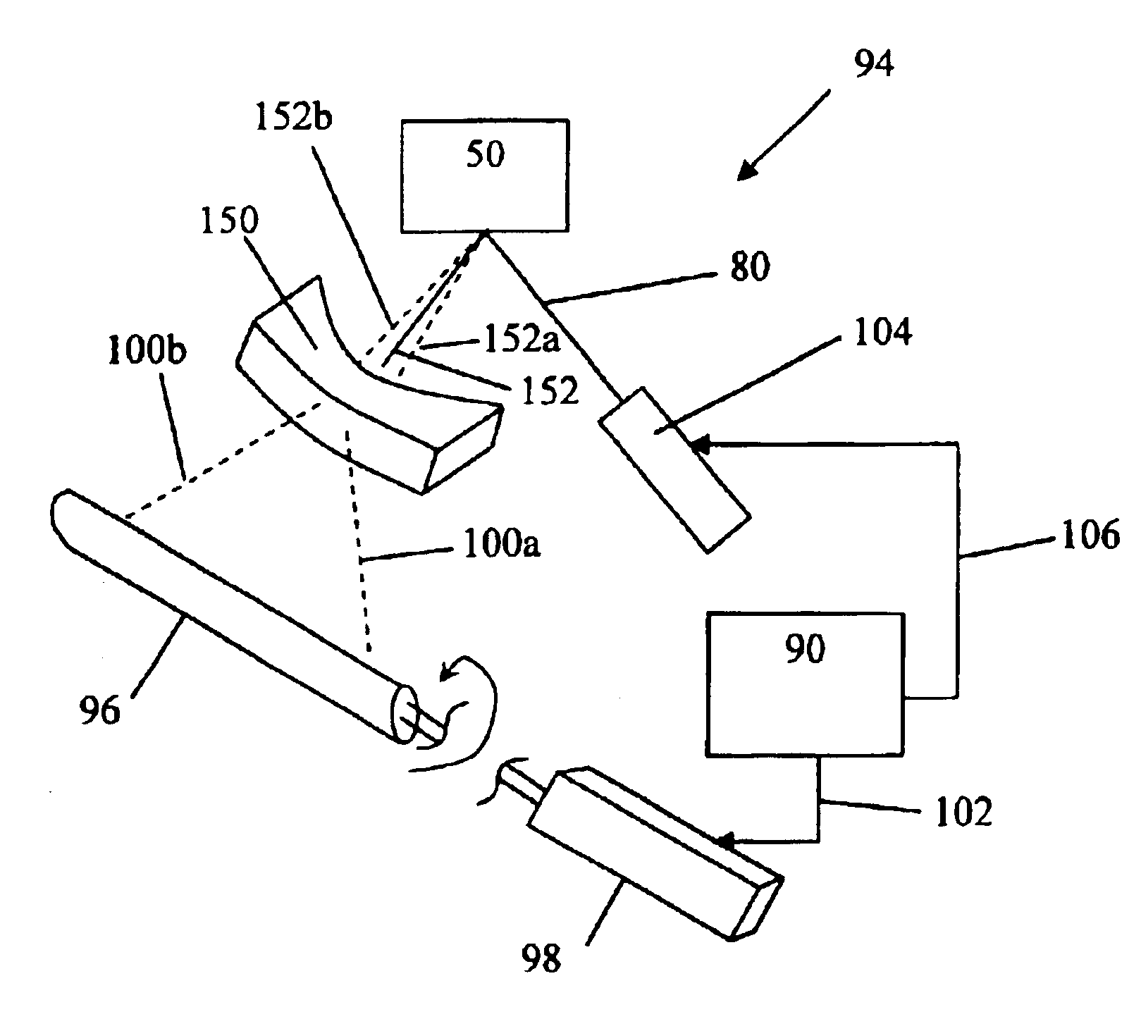
[0005]The above discussed embodiment provides a method of synchronizing multiple oscillating scanners such as would be found in a color laser printer. This allows the relatively inexpensive oscillating scanners to be used as opposed to the rotating polygonal mirrors previously employed. In addition, manipulating the phase and amplitude of the drive signal ensures a uniform process speed can be maintained by the independent scanners acting in tandem.
[0008]The above discussed embodiment of the present invention improves control of the oscillation of the oscillating scanners by manipulating the phase and amplitude of the drive signal provided to each oscillating scanner. In particular, the phase and amplitude of the drive signal are manipulated to compensate for the oscillating scanners that experience changes in their resonant frequency.

Problems solved by technology

Unfortunately, the rotating polygonal mirror scanners are relatively expensive devices that are difficult to control and increase the cost of the laser printer.
Unfortunately, each oscillating scanner operates best at or near its resonant frequency and the resonant frequency of the device changes in response to a number of factors.
Therefore, in general, these devices have previously been less desirable for use in devices that require all of the scanning members to operate in unison.

Method used


Image

  • Scanning with multiple oscillating scanners
  • Scanning with multiple oscillating scanners
  • Scanning with multiple oscillating scanners

Examples


Embodiment Construction

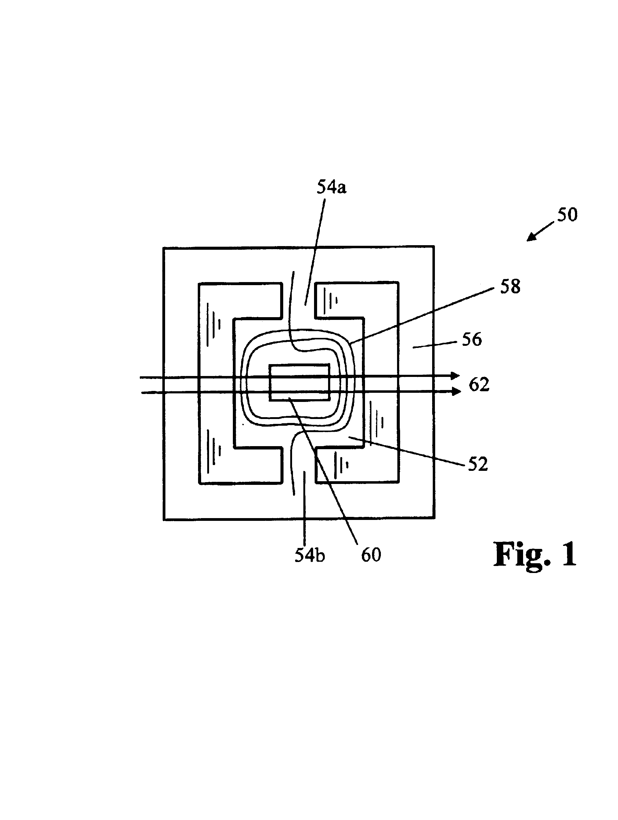
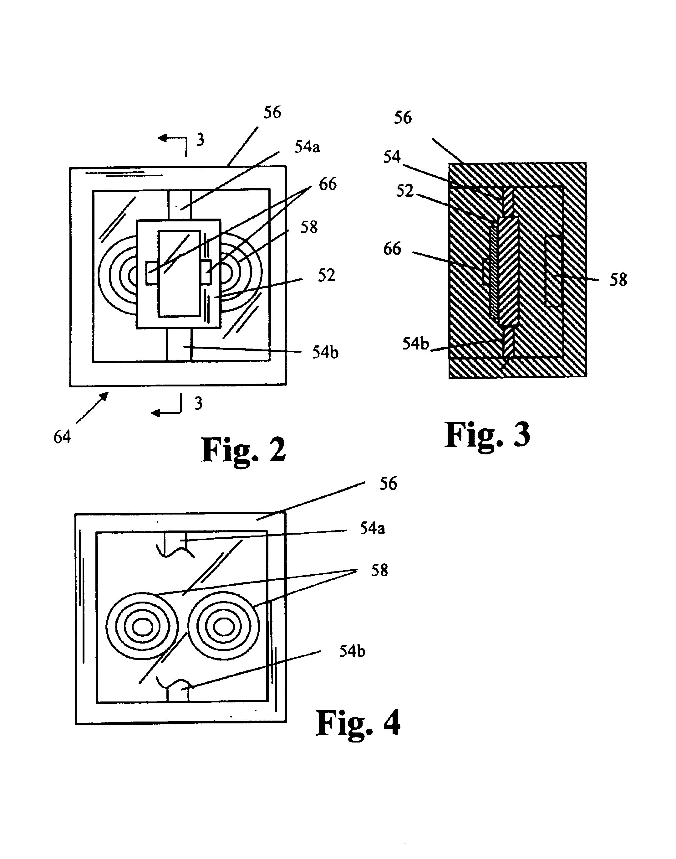
[0049]Preferred embodiments of the present invention utilize a torsion oscillator. The torsion oscillator 50 of FIG. 1 comprises a central generally rectangular plate 52 suspended by two extensions 54a, 54b of the material of plate 52. The plate 52 is generally symmetrical about its axis of oscillation. Extensions 54a, 54b are integral with a surrounding frame 56. Typically, the plate 52, extensions 54a, 54b and frame 56 are cut or etched from a single silicon wafer. A coil 58 of conductive wire and a mirror 60 or similar reflective surface are placed on the central plate. The mirror may be a smooth or polished surface on the silicon plate 52, since silicon itself is about sixty percent reflective Typically the mirror is a deposited layer of gold (or other material) on the smooth silicon substrate. Since the reflectivity of the silicon is wavelength dependent (falling off rapidly about 1 micron wavelength), a deposited mirror is typically used, or the raw silicon can be used without...


PUM


Abstract

A method and device for managing and controlling a scanning system that incorporates multiple oscillating scanners is provided by the present invention. In accordance with the preferred embodiment, a resonant frequency is determined for each of the scanners. A drive signal for driving the oscillating scanners is generated based upon the determined resonant frequencies. An amplitude adjustment circuit determines the difference between the drive signal frequency and the resonant frequency of each oscillating scanner and adjusts the amplitude of the drive signal provided to that particular oscillating scanner such that scan amplitude of each oscillating scanner is approximately equal. The offset from the resonant frequency is also used to calculate a phase adjustment for the drive signal to insure that the oscillating scanners are operating in tandem.

Description

FIELD OF THE INVENTION[0001]The present invention is generally directed to systems using multiple oscillating scanners. More particularly, the invention is directed toward a method and apparatus for insuring that multiple oscillating scanners are operating at the same scan rate.BACKGROUND OF THE INVENTION[0002]A tandem printer utilizes multiple exposure stations to develop a full color image. For example, in many color laser printers, the exposure is accomplished through the use of four independent laser scanning units. Each laser scanning unit incorporates it's own rotating polygonal mirror scanner and all four of the polygonal scanners are designed to have the same general scanning speed. Unfortunately, the rotating polygonal mirror scanners are relatively expensive devices that are difficult to control and increase the cost of the laser printer.[0003]Oscillating type scanners are also used to scan lasers along a scan path. These types of oscillating scanners are typically less ex...

Claims


Application Information

Patent Timeline
Patent Type & Authority Patents(United States)
IPC IPC(8): B41J2/435B41J2/47
CPCB41J2/47
Inventor BUSH, CRAIG P.CANNON, ROGER S.KLEMENT, MARTIN C.WARD, E. DAWSON
Owner LEXMARK INT INC
Learn More