
Thermometer implants

Inactive Publication Date: 2005-10-11
REIFFEL TECH
View PDF9 Cites 3 Cited by
  • Summary
  • Abstract
  • Description
  • Claims
  • Application Information

AI Technical Summary

Benefits of technology

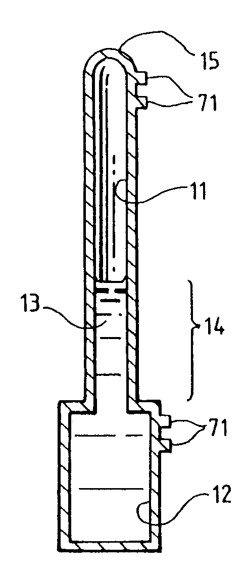
[0005]One form of this invention of thermometer implants comprises a thermometer body, the thermometer body enclosing a channel and a bulb, the channel being terminated by the bulb at one end, the channel and the bulb containing a fluid, the fluid expanding and contracting along the channel to a fluid length which is functionally related to a target temperature of the bulb at a target time, the thermometer body being located in a subject body from where the fluid length is not visible at the target time, and thermometer body properties and fluid properties together making possible measurement of the fluid length outside of the subject body.

Problems solved by technology

Since existing temperature sensors are not adequate to the task, workers have long been seeking new ways to measure the temperature for such cases.

Method used


Image

  • Thermometer implants
  • Thermometer implants

Examples


Embodiment Construction

[0011]A cross section of a basic form 10 of a thermometer implant is shown in FIG. 1. This basic form comprises a thermometer body 15 which encloses a channel 11 terminated at one end by a bulb 12 with a fluid 13 contained in the bulb and the channel. As the temperature of the bulb increases and decreases the fluid 13 expands and contracts along the channel to a fluid length 14 which is functionally related to a target temperature of the bulb at a target time. The target time is a time when temperature data is desired, and the target temperature is the temperature of the bulb at the target time.

[0012]Dimensions of an example thermometer implant which can be implanted in living tissue—for example by using standard biopsy techniques—are: length of thermometer 20 mm; channel inside diameter 50 microns; bulb length 5 mm; bulb inside diameter 0.75 mm; bulb outside diameter 1.25 mm; thermometer outside diameter away from bulb 90 microns. A suitable fluid in a thermometer with these dimens...


PUM


Abstract

A thermometer implant (10), especially useful in medical diagnostic and therapeutic procedures, comprises a thermometer body (15) containing a fluid (13) which expands, and contracts to a fluid length (14) that indicates a target temperature at a target time, and which is located in a body from where the expanding fluid is not visible at the target time, with the fluid length (14) at the target time being measured outside the body.

Description

BACKGROUND OF THE INVENTION[0001]A thermometer implant—especially useful in medical diagnostic and therapeutic procedures—comprises a thermometer body containing a fluid which expands and contracts to a fluid length which indicates a target temperature at a target time and which is located in a body from where the fluid length is not visible at the target time, with the fluid length at the target time being measured outside the body.[0002]When, for example, a cancerous tumor is treated by hyperthermia or cryotherapy it is very important to control the temperature in the tumor as well as the temperature in healthy tissue. Since existing temperature sensors are not adequate to the task, workers have long been seeking new ways to measure the temperature for such cases.[0003]An implanted reflector which reflects a microwave signal as a function of temperature is shown by Nowogrodzki in U.S. Pat. No. 4,138,998. An implanted element which has temperature dependent nuclear magnetic resonan...

Claims


Application Information

Patent Timeline
IPC IPC(8): A61B5/01G01K5/00G01K5/02A61B5/00G01K1/06
CPCA61B5/01G01K1/065G01K5/02
Inventor REIFFEL, LEONARD
Owner REIFFEL TECH
Learn More