
Proton precession magnetometer sensor measurable in all direction

a magnetometer sensor and protons are applied in the field of protons precession magnetometer sensors, which can solve the problems of inconvenient optical pumping magnetometers, inconvenient manufacturer direct tuning, and experimentally vulnerable overhauser effect magnetometers to ambient nois

Active Publication Date: 2011-03-31
KOREA INST OF GEOSCI & MINERAL RESOURCES
View PDF8 Cites 3 Cited by
  • Summary
  • Abstract
  • Description
  • Claims
  • Application Information

AI Technical Summary

Benefits of technology

[0013]To solve the above described problems, an aspect of the present invention is to provide a proton precession magnetometer sensor in which measurement is possible in all directions since there is no low-sensitivity angle (i.e., there is no dead band).
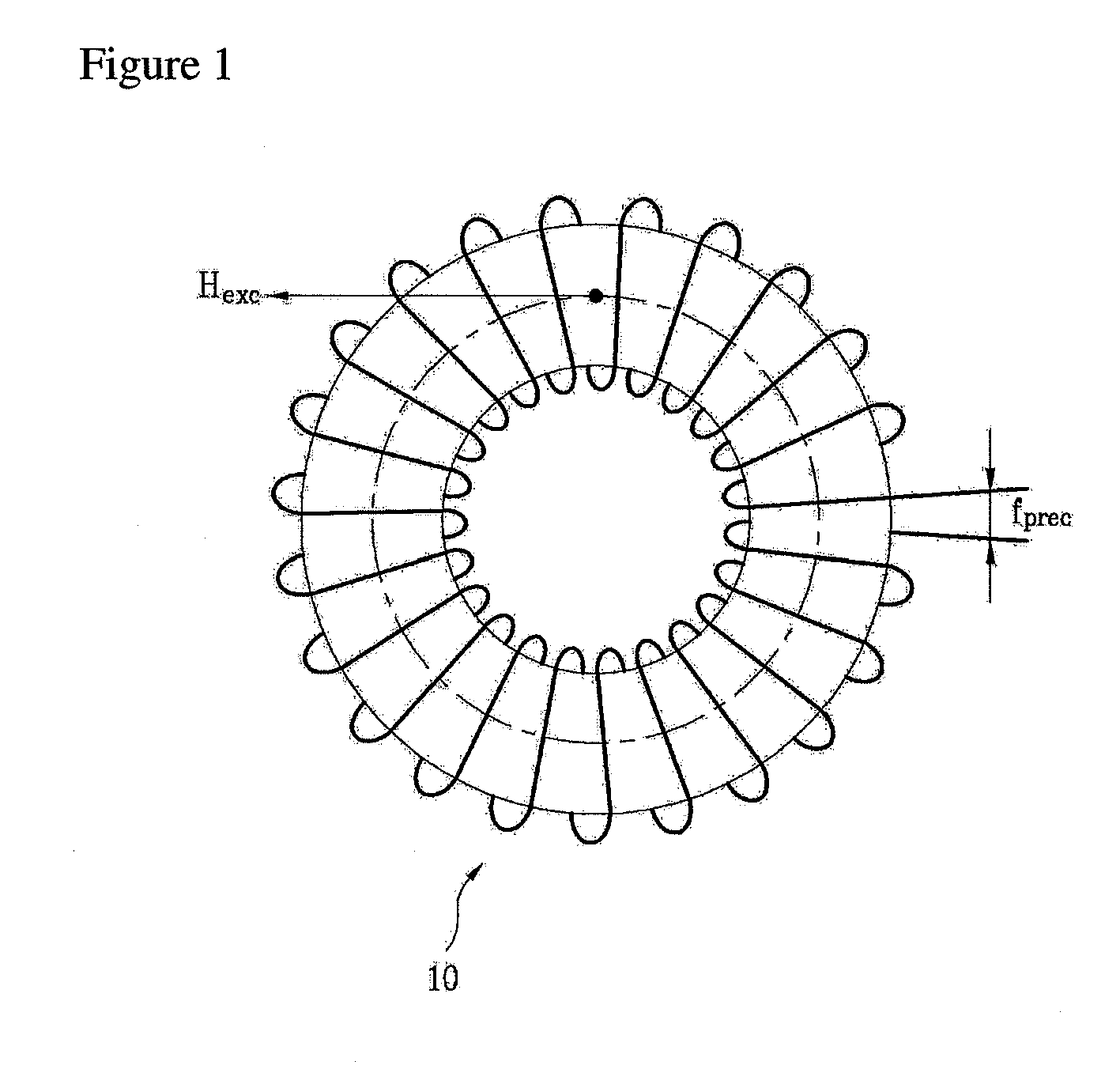
[0016]According to an exemplary embodiment of the present invention, a proton precession magnetometer sensor can measure an external magnetic field in all directions because there is no dead band. Therefore, it is convenient to measure the external magnetic field because there is no need of adjusting the sensor to a certain direction when measuring magnetic force.

Problems solved by technology

The Overhauser effect magnetometer is experimentally vulnerable to ambient noise such as 60 Hz power line or the like.
The optical-pumping magnetometer is inconvenient in that it needs direct-tuning of a manufacturer again for replacement since a current technology level cannot strictly predict a lifespan of an internal lamp.
However, such methods for measuring a magnetic field using the principle of proton precession has a limit that a low-sensitivity angle (i.e., a dead band) exists at a certain direction where the measurement is not impossible.
On the other hand, the induced voltage decreases as the two magnetic fields get more parallel with each other, and therefore it is difficult to measure the frequency.

Method used


Image

  • Proton precession magnetometer sensor measurable in all direction
  • Proton precession magnetometer sensor measurable in all direction
  • Proton precession magnetometer sensor measurable in all direction

Examples


Embodiment Construction

[0024]Hereinafter, exemplary embodiments of the present invention will be described with reference to accompanying drawings. However, the present invention is not limited to the embodiments set forth herein and may be embodied in different forms. Rather, the embodiments introduced herein are provided so that disclosed contents will be thorough and complete, and will fully convey the spirit of the invention to those skilled in the art. Like numbers refer to like elements throughout the figures.

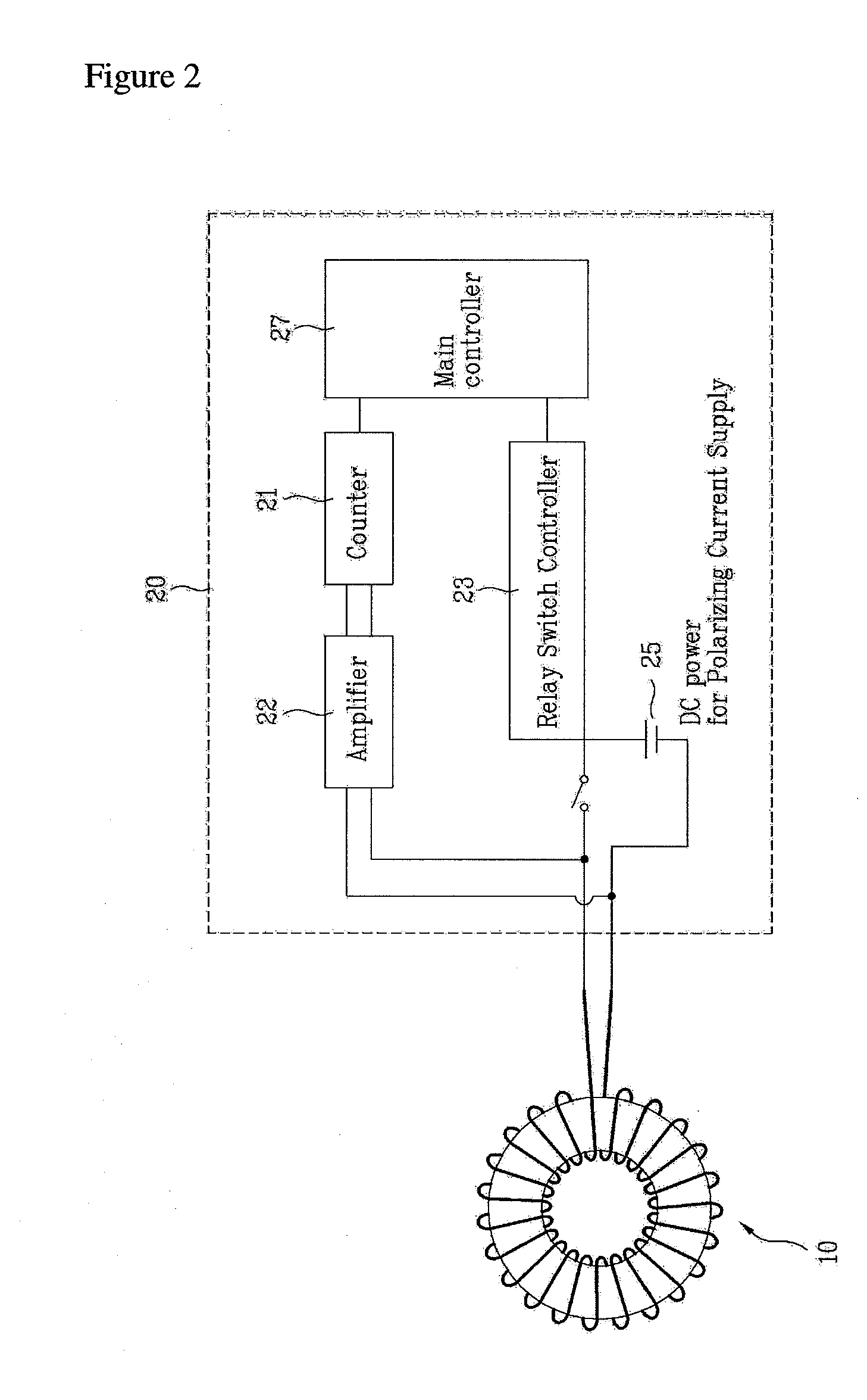
[0025]FIG. 1 is a schematic view of a proton precession magnetometer sensor capable of all-direction measurement according to an exemplary embodiment of the present invention. As shown therein, a proton precession magnetometer sensor 10 according to an exemplary embodiment of the present invention employs a toroid coil 12 as a coil, in which frequency (this is equal to frequency (fprec) of precession of a proton) of current induced in the toroid coil 12 is measured to calculate the strength of ...


PUM


Abstract

A “proton precession magnetometer sensor capable of all-direction measurement” according to the present invention, in which frequency of current induced in a coil by flowing and then breaking current in the coil is measured to calculate strength of an external magnetic field, is characterized in that the coil is a toroid coil. Alternatively, the coil may be achieved by two solenoid coils connected perpendicularly, or N solenoid coils connected in the form of a polygon, where N is an integer of 3 or more. The proton precession magnetometer sensor is capable of measuring the external magnetic field in all directions since there is no dead band, and is convenient since there is no need of adjusting the sensor to a certain direction when measuring magnetic force. Further, the present invention will bring accumulation of key original technology applicable to various cases in practice through development of improved impedance matching and power consumption optimization in future practice.

Description

BACKGROUND OF THE INVENTION[0001]1. Field of Invention[0002]The present invention relates to a proton precession magnetometer sensor which senses strength of a magnetic field by measuring frequency of current induced in a coil due to a break of strong current after flowing the strong current in the coil.[0003]2. Description of Related Art[0004]In geophysical prospecting, a magnetic survey is a method that provides fundamental and important information for a reconnaissance survey and a detail survey. To this end, a 3-axis fluxgate magnetometer, a proton precession magnetometer, an Overhauser effect magnetometer, an optical-pumping magnetometer, etc. are employed as a magnetometer for surface and aerial surveys.[0005]The fluxgate magnetometer is capable of measuring vector components, but its temperature drift characteristic or orthogonality is not precise. The Overhauser effect magnetometer is experimentally vulnerable to ambient noise such as 60 Hz power line or the like. The optica...

Claims


Application Information

Patent Timeline
Patent Type & Authority Applications(United States)
IPC IPC(8): G01R33/24
CPCG01R33/04G01R33/028G01R33/02
Inventor JUNG, HYUN KEYLIM, MU TAEKSON, JEONGSULRIM, HYONG REA
Owner KOREA INST OF GEOSCI & MINERAL RESOURCES
Learn More