
Disk cartridge and manufacturing method thereof

Inactive Publication Date: 2005-10-04
SONY CORP
View PDF8 Cites 3 Cited by
  • Summary
  • Abstract
  • Description
  • Claims
  • Application Information

AI Technical Summary

Benefits of technology

[0011]According to the disk cartridge and the manufacturing method thereof described above, use of two types of thermoplastic resin, each having a heat-deforming temperature different from the other, enables to mix the two types of resin with anti-static polymer in a stable range of temperatures lower than the decomposition temperature of the polymer. Furthermore, thermoplastic resin mixed with inorganic filler can improve strength of the disk cartridge.

Problems solved by technology

Thus, it is difficult to keep the anti-static property on the surfaces of the upper and lower halves for a long time.
When mixing PC (polycarbonate) resin, a high heat-resistant thermoplastic resin, with the anti-static polymer material in uniform, however, the mixing must be done at high temperatures, so that such a problem is caused that the polymer material loses the anti-static property.
The use of low heat-resistant thermoplastic resin may solve this problem, but this will also cause another problem.
However, unless the thermoplastic resin in use flows well in its injection molding, the molding accuracy of the upper and lower halves is lowered and in some cases, the injection-molding itself is disabled.
Furthermore, when there is any residual distortion in the upper and lower halves after the injection-molding, in the disk cartridge comprising the upper and lower halves and being kept to be subjected to high temperatures, there is a fear of a problem that the residual strain develops in relaxation to cause the upper and lower halves to be deformed to disable the normal use of the disk cartridge.

Method used


Image

  • Disk cartridge and manufacturing method thereof
  • Disk cartridge and manufacturing method thereof
  • Disk cartridge and manufacturing method thereof

Examples


Embodiment Construction

[0017]Hereunder, preferred embodiments of this invention will be described in detail with reference to attached drawings.

[0018]The embodiments to be described below are preferred ones according to the present invention with various technical restrictions applied thereto. The scope of the present invention, however, is not limited to the embodiments unless otherwise described.

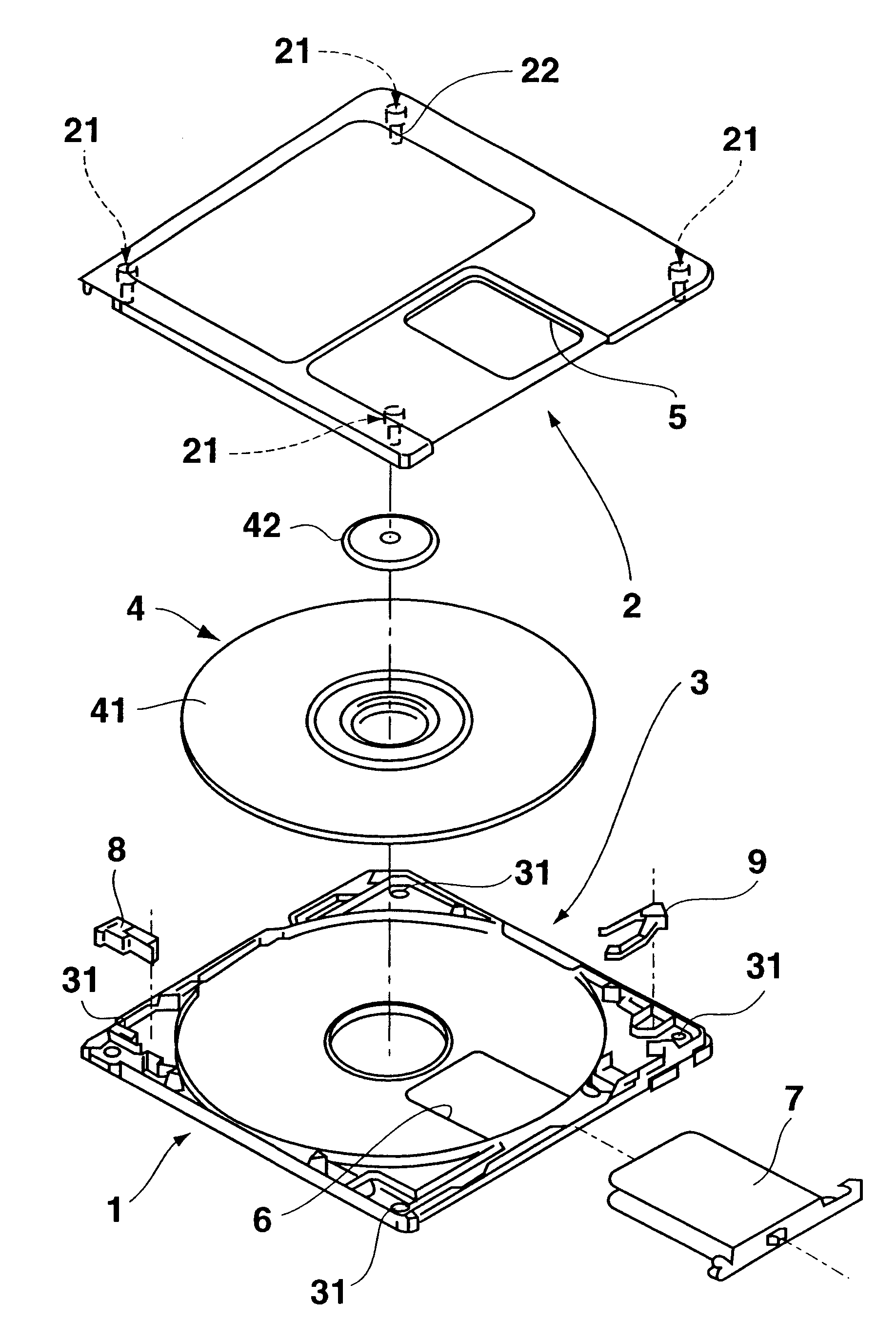
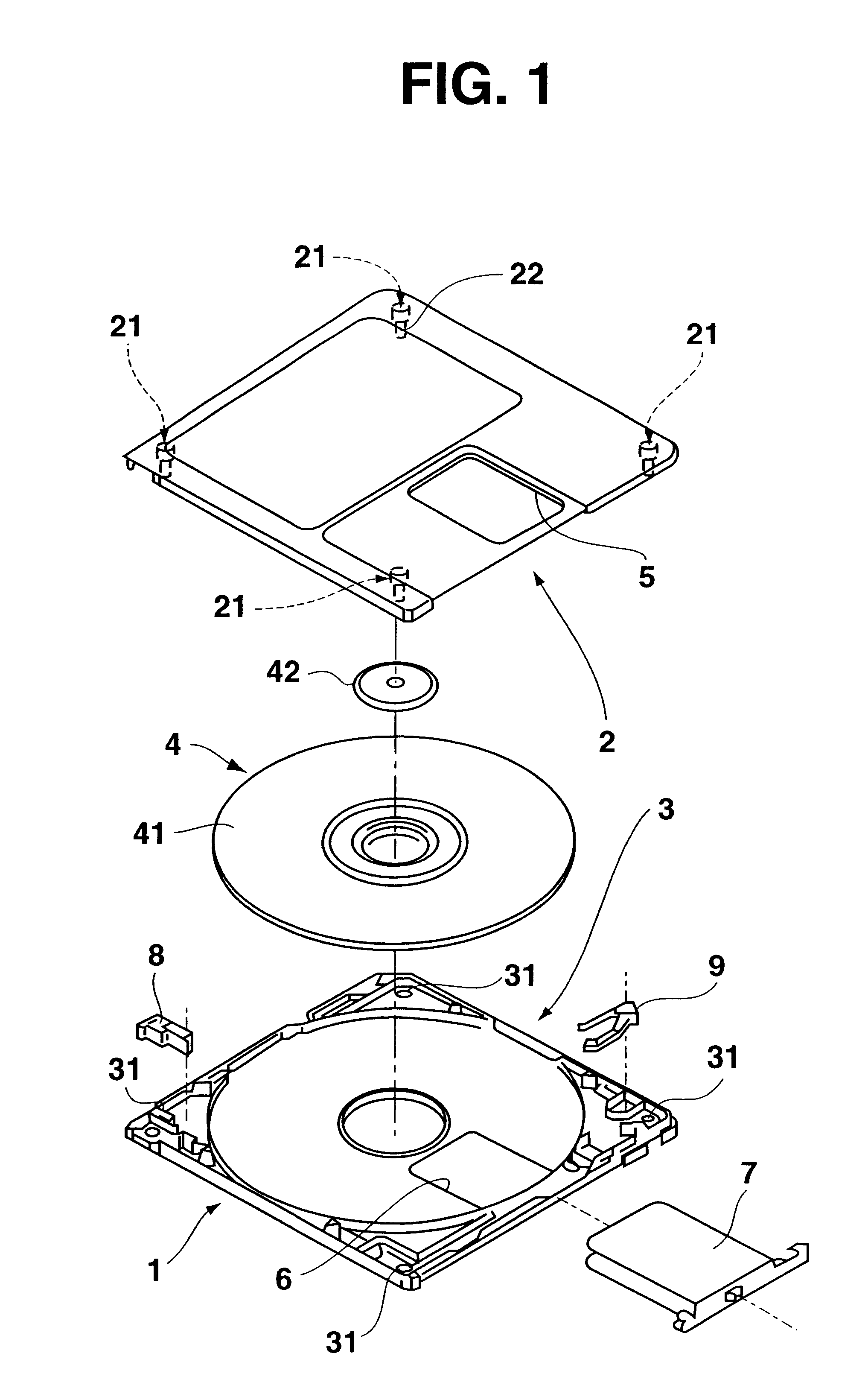
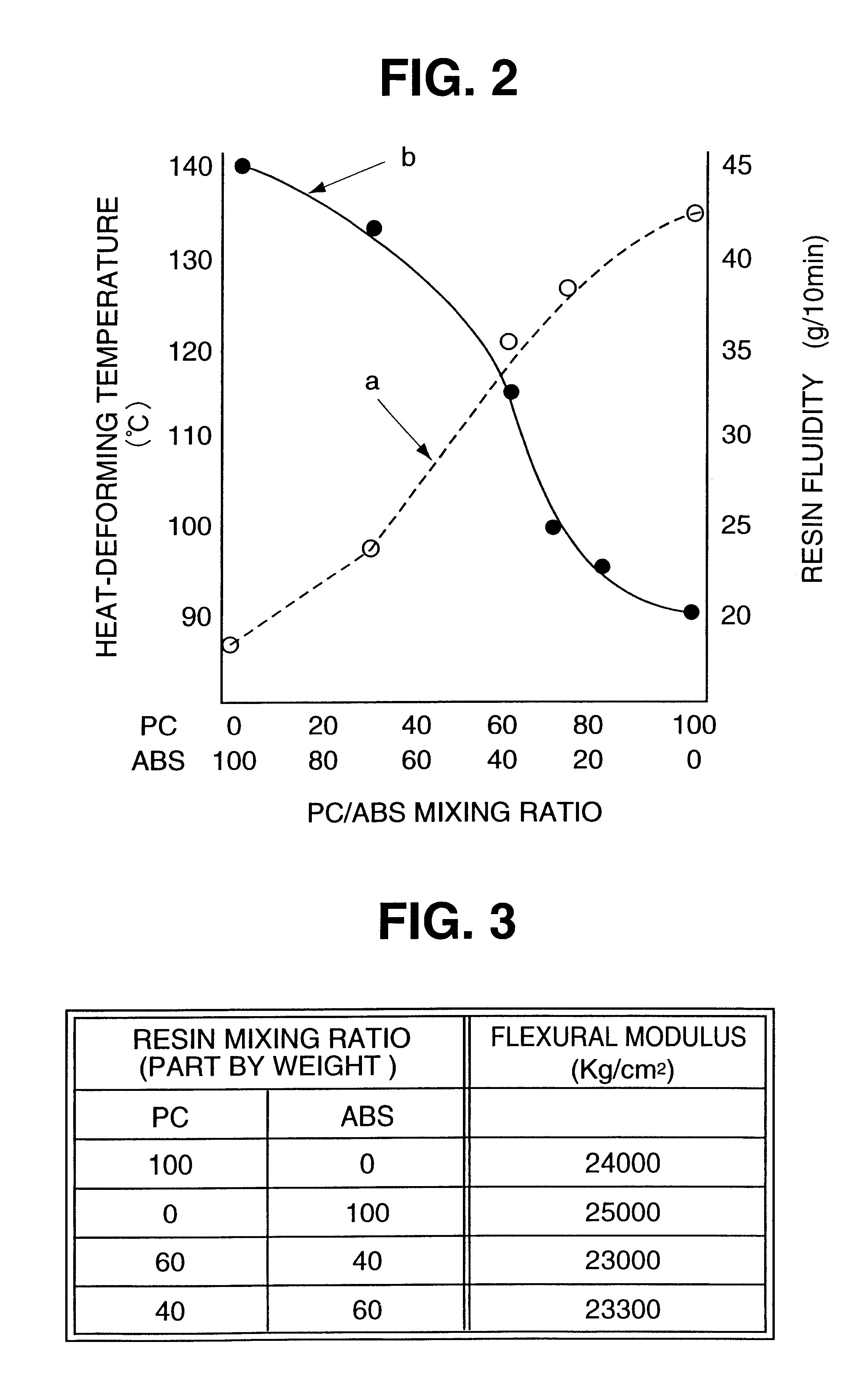
[0019]FIG. 1 is an exploded perspective view of a disk cartridge according to an embodiment of the present invention. In this disk cartridge 1, a disk 4 of an optical disk or a magnet-optical disk is rotatably mounted between an upper half 2 and a lower half 3 both made of synthetic resin with the upper and lower halves coupled. A sliding shutter 7 is provided to the disk cartridge for being used to open / close both the opening 5 provided to the upper half 2 and the opening 6 provided to the lower half 3.

[0020]Between the upper and lower halves 2 and 3 are disposed a safety member 8 slidably provided for preventi...


PUM

PropertyMeasurementUnit
Percent by massaaaaaaaaaa

Abstract

A disk cartridge in which a disk is loaded is formed with composite synthetic resin including at least two types of thermoplastic resin, an anti-static polymer, and an inorganic filler, heat-deforming temperatures of at least two types of the thermoplastic resin mutually differing.The disk cartridge is provided by a method comprising the steps of mixing at least two types of thermoplastic resin to provide a mixture, heat-deforming temperatures of at least two types of the thermoplastic resin mutually differing, mixing an inorganic filler with a mixture of at least two types of the thermoplastic resin, mixing an anti-static polymer with the mixture of at least two types of the thermoplastic resin including the inorganic filler to provide a composite synthetic resin, injection molding the composite synthetic resin to provide component parts of the disk cartridge, and assembling the component parts to form the disk cartridge with the disk loaded therein.

Description

BACKGROUND OF THE INVENTION[0001]The present invention relates to a disk cartridge in which such a disk as an optical disk and an optical magnetic disk is rotatably mounted which can reproduce and / or record data.[0002]The disk cartridge loaded with the disk mentioned above is used widely as an external recording medium for audio devices or computers. Such a disk cartridge comprises an upper half and a lower half that are made of synthetic resin and coupled to each other. In other words, a weld rib provided at the tip of a coupling projection of the upper half is pressed against the tip of a coupling recess of the lower half, then fused by ultrasonic waves, so that the coupling projection is welded to the coupling recess to couple the upper half to the lower half. Both upper and lower halves are molded with injected thermoplastic resin such as polycarbonate with high heat-resistance and high rigidity.[0003]The upper and lower halves of a conventional disk cartridge has the following ...

Claims


Application Information

Patent Timeline
IPC IPC(8): G11B23/02G11B23/04
CPCG11B23/045Y10T428/1352G11B23/113G11B23/0315G11B23/021G11B2220/2525
Inventor KIKUCHI, SHUICHIKOBAYASHI, DAIKIOGISU, KENJI
Owner SONY CORP
Learn More