
Enabling a service provider to provide intranet services

Inactive Publication Date: 2005-09-20
INTELLECTUAL VENTURES I LLC
View PDF130 Cites 114 Cited by
  • Summary
  • Abstract
  • Description
  • Claims
  • Application Information

AI Technical Summary

Benefits of technology

[0020]The present invention allows providers of virtual servers to properly differentiate and route transmissions using private addresses on a common host server. The term “private virtual server” as used herein is a virtual server that supports a private address space wherein the private address spaces of different private virtual servers may overlap.
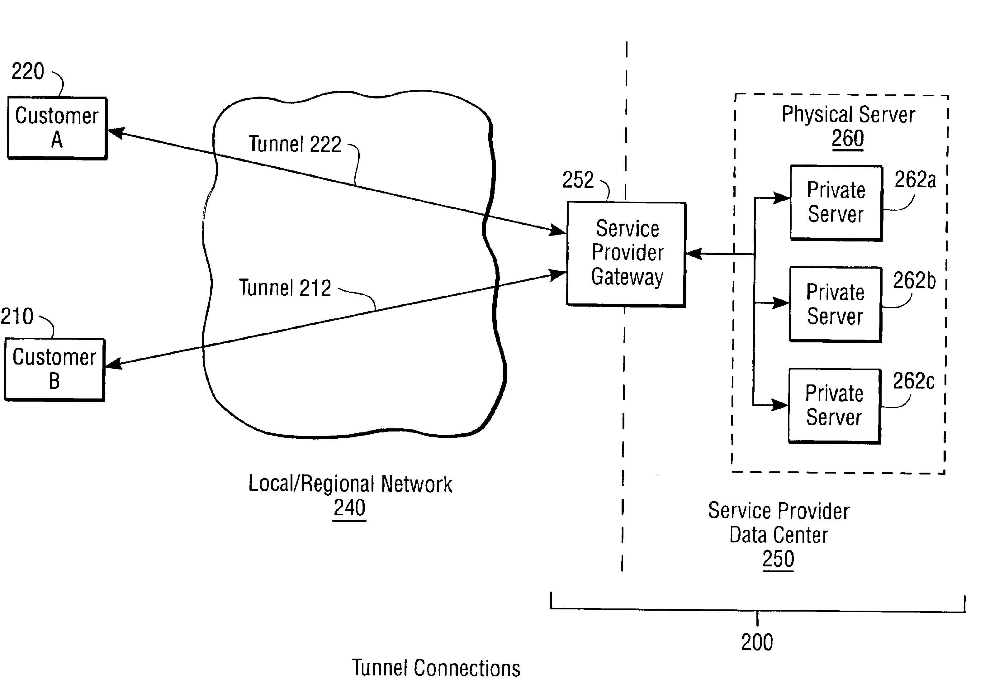
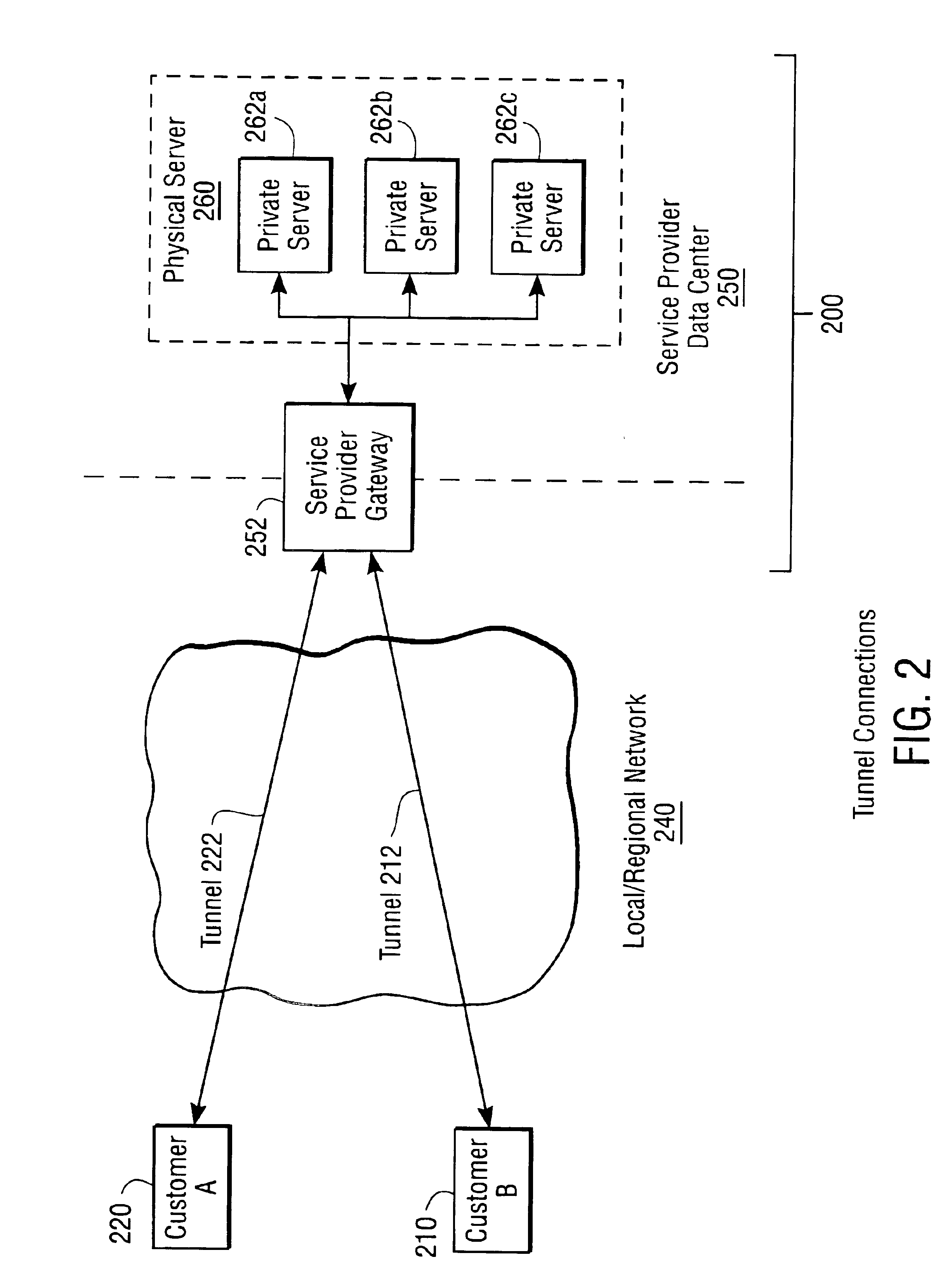
[0021]Customers exchange privately-addressed transmissions with a service provider using tunnels to traverse the local or regional network connecting the customer with the service provider. The service provider receives the transmissions at a gateway into the service provider's data center. The service provider then routes the transmission to the private virtual server belonging to the customer that sent the transmission. The service provider also routes privately-addressed transmissions back to individual customers using tunnels. In this way, the service provider is able to implement a separate routing context on behalf of each individual customer.
[0022]The present invention allows for flexibility in designing a private virtual server that suits an individual customer's needs. For example, an individual customer may have multiple physical sites all utilizing the same private virtual server. Optionally, an individual customer may be assigned more than one private virtual server, for instance, if different divisions of an organization each wish to maintain their own private servers while making all the data available to the organization at large.
[0023]In one embodiment, the present invention comprises a multiplexing / demultiplexing mechanism capable of routing signals to and from one or more private virtual servers located on a physical host computer. Each private virtual server is associated with only one private network. The multiplexing / demultiplexing mechanism receives a privately addressed transmission and routes it to the private virtual server with which it is associated. The privately addressed transmission may then be processed within the private virtual server in the same manner as if the server was actually a physical server resident within a LAN. The multiplexing / demultiplexing mechanism also receives an outgoing transmission from a private virtual server and routes it back to the private network associated with it. Incoming and outgoing transmissions are addressed using a tunneling scheme. Tunneling allows privately-addressed transmissions to be transported over a network that uses global addresses and allows customers to address their private virtual server using a non-unique private address. As a result, all transmissions to and from a customer are sent only to the customer's respective private virtual server.

Problems solved by technology

Data communications services and servers are not easy to configure, manage, and maintain.
It is not economically feasible for a service provider to remotely manage servers located on a customer's premises, and support many different customers in this fashion.
However, this means the service provider will have to own and maintain potentially large numbers of physical host computers, at least one for each customer's server or private network However, many customers will neither require nor be amenable to paying for the use of an entire host computer.
However, virtual hosting it is commonly performed today does not provide many of beneficial features of private networks.
Additionally, faults, crashes, or similar problems caused by one customer must not compromise the service provided to another customer.
Also, public IP addresses are a limited resource; there is insufficient address space for private networks to consume addresses from the public address space.
However, the use of private address schemes creates difficulties for the service provider.
This address overlap can cause the communication network to fail.
Typically, one of the virtual servers would become unreachable due to this address overlap error.
Virtual hosting currently cannot provide these beneficial features of ordinary private servers.
This is due to the inability of a virtual host to allocate appropriate amounts of computer resources of the physical host computer to servicing client requests made to specific virtual hosts, and hence to specific customers.

Method used


Image

  • Enabling a service provider to provide intranet services
  • Enabling a service provider to provide intranet services
  • Enabling a service provider to provide intranet services

Examples


Embodiment Construction

[0040]Reference will now be made in detail to several embodiments of the present invention, examples of which are illustrated in the accompanying drawings. Wherever practicable, the same reference numbers will be used throughout the drawings to refer to the same or like parts. The figures depict preferred embodiments of the present invention for purposes of illustration only. One skilled in the art will readily recognize from the following discussion that alternative embodiments of the structures and methods illustrated herein may be employed without departing from the principles of the invention described herein.

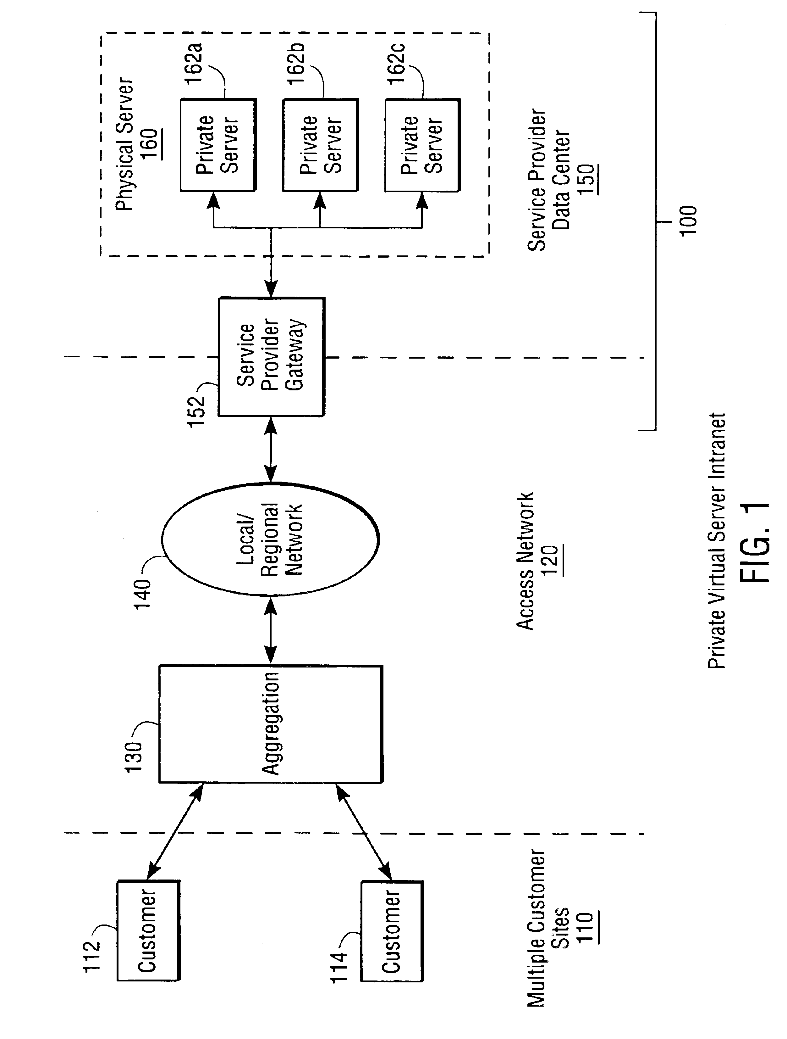
[0041]FIG. 1 is an illustration of an embodiment of a private virtual server system, which replaces multiple private Intranet servers. A private virtual server system 100 includes a service provider gateway 152 that connects to a service provider data center 150. System 100 is connected to multiple customer sites 110 via an access network 120. Customers, e.g. 112 and 114, a...


PUM


Abstract

A method and system allows a service provider to provide Intranet services remotely by assigning private virtual servers to customers. Each customer addresses transmissions to one or more private virtual servers using private addresses from the customer's private Intranet. The addresses of different private virtual servers do not have to be unique and may overlap. Customers exchange privately-addressed transmissions with the service provider using tunnels to traverse the local or regional network connecting the customer with the service provider. The service provider routes the transmissions to the relevant private virtual server belonging to the customer that sent the transmission. The service provider also routes privately-addressed transmissions back to individual customers using tunnels.

Description

CROSS REFERENCE TO RELATED APPLICATIONS[0001]This application is related to U.S. patent Ser. No. 09 / 452,286, entitled “Providing Quality of Service Guarantees to Virtual Hosts”, by Pawan Goyal et al., filed Nov. 30, 1999, and commonly assigned with the present application. The subject matter of related application U.S. patent Ser. No. 09 / 452,286 is incorporated by reference herein in its entirety.BACKGROUND[0002]1. Field of Invention[0003]the present invention relates generally to providing private networking services, e.g., Intranet services, remotely, and more particularly, to allowing a service provider to locate and manage private network servers at the service provider's location, while connecting the servers to a customer's premises such that they appear to be local and private to the customer.[0004]2. Background of the Invention[0005]Networked computer resources are growing more popular as the benefits of sharing computing resources becomes evident. One of the fastest-growing...

Claims


Application Information

Patent Timeline
IPC IPC(8): G06F15/16H04L12/24H04L29/08
CPCH04L41/18H04L41/5064H04L67/2814H04L2212/0025H04L2212/00H04L67/563
Inventor NEWMAN, PETERGOYAL, PAWAN
Owner INTELLECTUAL VENTURES I LLC
Learn More