
Method and apparatus for processing packets in a routing switch

a routing switch and packet processing technology, applied in the field of data transport, can solve the problems of not meeting the traffic demands of newly implemented networks, the current architecture of routing switches is failing to meet the needs of data traffic, and the current generation of routing switches has become increasingly complex in the communication and computational overhead required

Inactive Publication Date: 2005-09-20
CIENA
View PDF16 Cites 23 Cited by
  • Summary
  • Abstract
  • Description
  • Claims
  • Application Information

AI Technical Summary

Benefits of technology

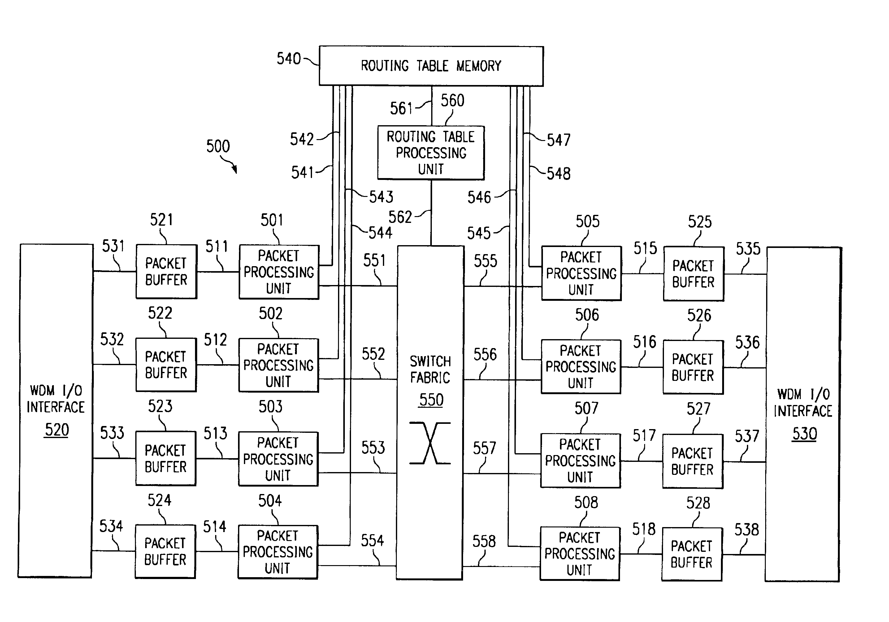
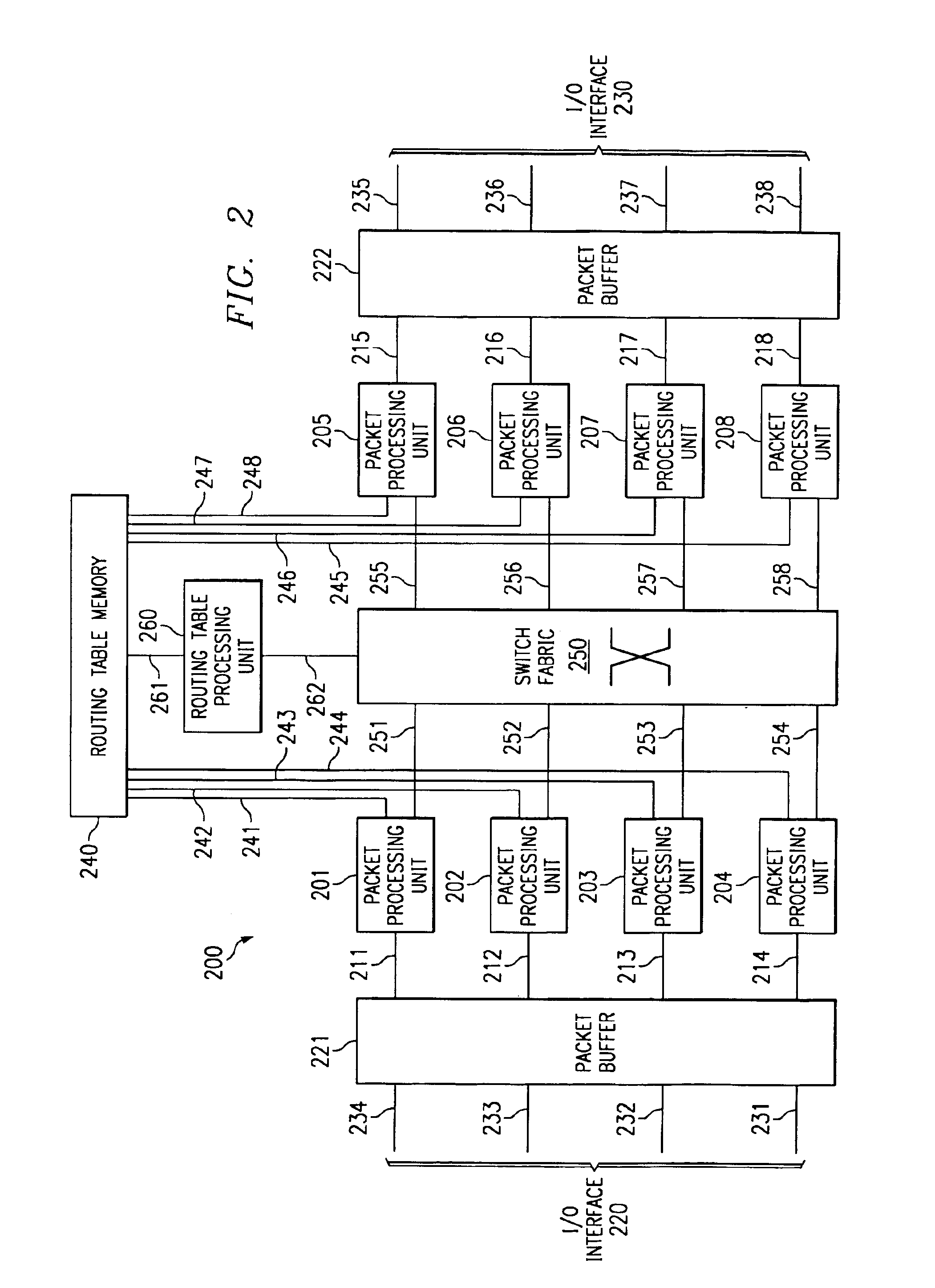
The patent describes a routing switch that uses a multiprocessor architecture to handle packets of data. The switch includes a switch fabric, a Routing Table Processing Unit, at least one packet buffer, at least one Packet Processing Unit, and a shared memory for storing a routing table. The Packet Processing Unit retrieves packets from the buffer and categorizes them as routing information packets or data packets. The routing information packets are forwarded to the Routing Table Processing Unit while the data packets are processed based on the information from the routing table. The switch includes a locking mechanism to synchronize the activities of the processing units. The technical effect of this invention is to provide a more efficient and reliable routing switch that can handle large amounts of data traffic and provide better synchronization between processing units.

Problems solved by technology

With the advent of optical networks, this methodology is beginning to fail to meet the traffic demands of newly implemented networks.
As optical networks are employed for higher density data traffic using increasingly more wavelengths per optical fiber, current architectures for routing switches are failing to meet the needs of this data traffic.
In addition, the current generation of routing switches have become increasingly complex in the communication and computational overhead required among its internal components.

Method used


Image

  • Method and apparatus for processing packets in a routing switch
  • Method and apparatus for processing packets in a routing switch
  • Method and apparatus for processing packets in a routing switch

Examples


Embodiment Construction

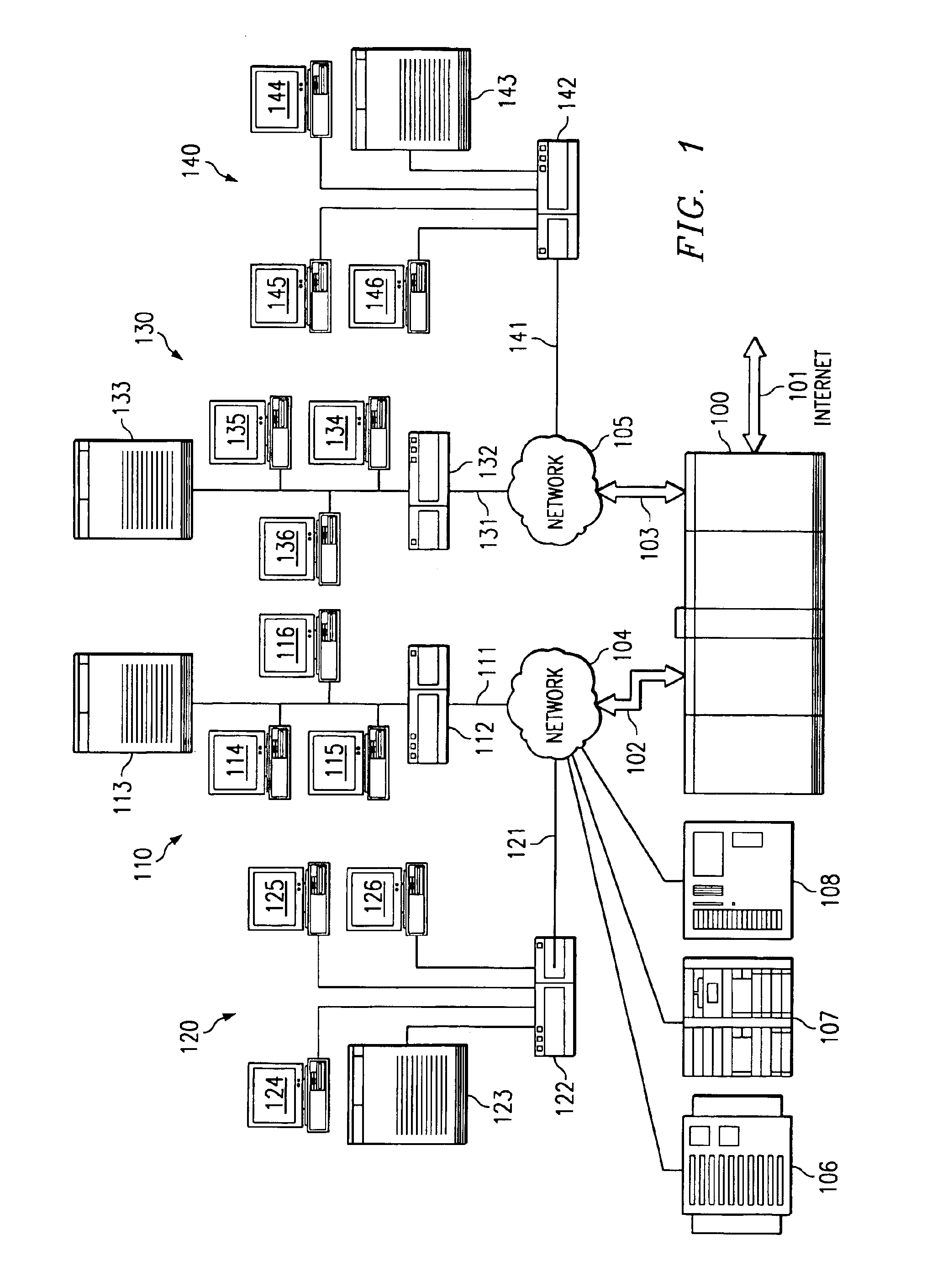
[0014]With reference now to FIG. 1, a pictorial representation of a distributed data processing system depicts a set of networks and internetwork connections in which the present invention may be implemented. Routing switch 100 is connected to the Internet via communications link 101. The Internet is a worldwide collection of networks and gateways that use the TCP / IP (Transport control Protocol / Internet Protocol) suite of protocols to communicate with one another. At the heart of the Internet is a backbone of high-speed data communication lines between major nodes or host computers consisting of thousands of commercial, government, educational, and other computer systems that route data and messages. Routing switch 100 is connected to network 104 by communications link 102, and routing switch 100 is connected to network 105 by communications link 103. Routing switch 100 provides a network interconnection between network 104, network 105 and the Internet.

[0015]Network 104 is connecte...


PUM


Abstract

A method, apparatus, and instructions for processing packets within a routing switch uses a multiprocessor architecture. The routing switch includes a switch fabric, a Routing Table Processing Unit, at least one packet buffer for queuing incoming and outgoing packets, at least one Packet Processing Unit, and a shared memory for storing a routing table. A Packet Processing Unit retrieves packets from a packet buffer memory, which may be a shared memory accessible to more than one of the Packet Processing Units depending upon the internal configuration of the components. The Packet Processing Unit categorizes the packets into routing information packets and data packets. The Packet Processing Unit forwards a routing information packet to a Routing Table Processing Unit and processes any other data packet by retrieving forwarding information from a routing table, updating the packet with the retrieved forwarding information, and forwarding the updated packet using a switch fabric connected to the Packet Processing Unit. A locking mechanism within the routing table memory provides synchronization between the activities of the various processing units. In response to receiving a routing information packet, the Routing Table Processing Unit locks a portion of the routing table, updates the locked portion of the routing table with information from the routing table information packet, and then unlocks the locked portion of the routing table. The Packet Processing Unit waits for a necessary portion of the routing table to be unlocked before retrieving any forwarding information. If more than one packet buffer memory is employed, the routing switch may be configured to support a wavelength division multiplexed (WDM) enabled network such that each input / output interface receives packets over a particular wavelength and queues the packets within separate packet buffers.

Description

FIELD OF THE INVENTION[0001]The present invention relates generally to data transport and, in particular, to a method and apparatus for sending and receiving data packets in a routing switch.BACKGROUND OF THE INVENTION[0002]With the explosive growth of data traffic on the Internet and corporate enterprise networks, corporations and Internet Service Providers (ISPs) demand faster routing switches that can meet the increasing traffic demands. However, in order to provide a high-speed device at a reasonable cost, manufacturers of routers and switches have generally met the demands for faster packet processing speeds and the demands of higher communication bandwidth by improving the hardware processing speed of each component within the routers and switches. With the advent of optical networks, this methodology is beginning to fail to meet the traffic demands of newly implemented networks.[0003]Gigabit routing speeds are required for meeting the bandwidth demands of higher capacity netw...

Claims


Application Information

Patent Timeline
Patent Type & Authority Patents(United States)
IPC IPC(8): H04L12/56H04L12/26
CPCH04L45/02H04L45/54H04L49/3009H04L49/3036
Inventor NAGARAJ, ALWARKURICHI PADMANA
Owner CIENA
Learn More