
Inkdrop printer with multi-segment printhead

a multi-segment, printhead technology, applied in the direction of printing, instruments, electric digital data processing, etc., can solve the problem that the solution does not scale well for the wider format printhead, and achieve the effect of wider pages, faster printing, and higher input resolution

Inactive Publication Date: 2005-09-20
SILVERBROOK RES PTY LTD
View PDF3 Cites 9 Cited by
  • Summary
  • Abstract
  • Description
  • Claims
  • Application Information

AI Technical Summary

Benefits of technology

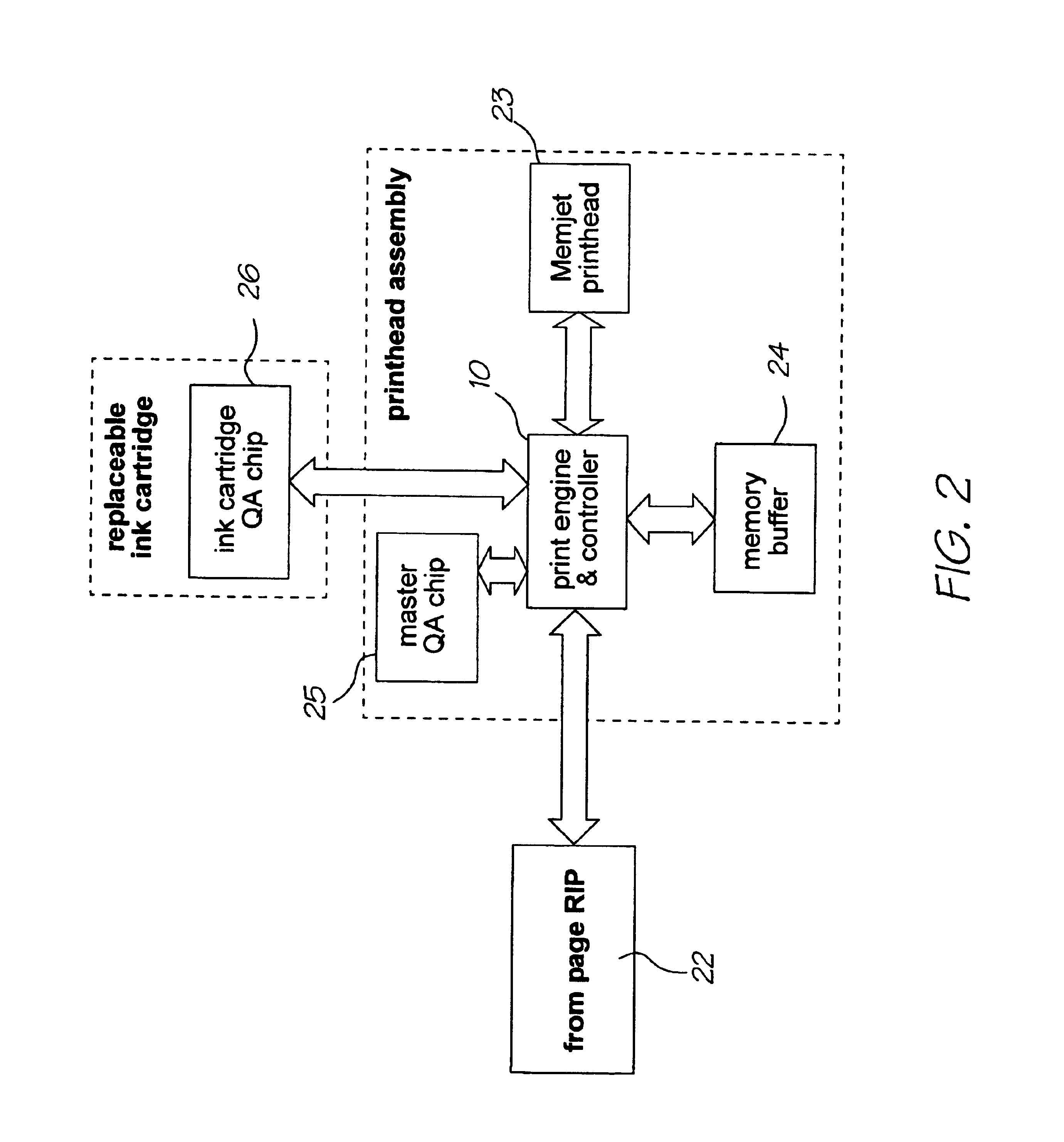
[0023]Synchronization can also be readily used for simultaneous duplex printing. One PEC prints 12 inches (15 segments) on one side of a page, while a second PEC simultaneously prints the second side of the page. As long as there is a single Master PEC chip giving the synchronization signals, combinations of PECs can be achieved.
[0024]Driving a single printhead from multiple chips is advantageous to produce wider pages, faster prints, higher input resolution, or combinations of all three.
[0025]To use multiple PECs, the same page can be given to multiple PECs. Different PECs then deal with strips of the page data, producing the total page in a faster time and / or higher resolution. A simple way of sending data to the printhead from multiple PECs is simply to have each PEC responsible for a given number of printhead segments.

Problems solved by technology

However this solution does not scale well for wider format printheads, for high resolution input images, or for faster printing.

Method used


Image

  • Inkdrop printer with multi-segment printhead
  • Inkdrop printer with multi-segment printhead
  • Inkdrop printer with multi-segment printhead

Examples


Embodiment Construction

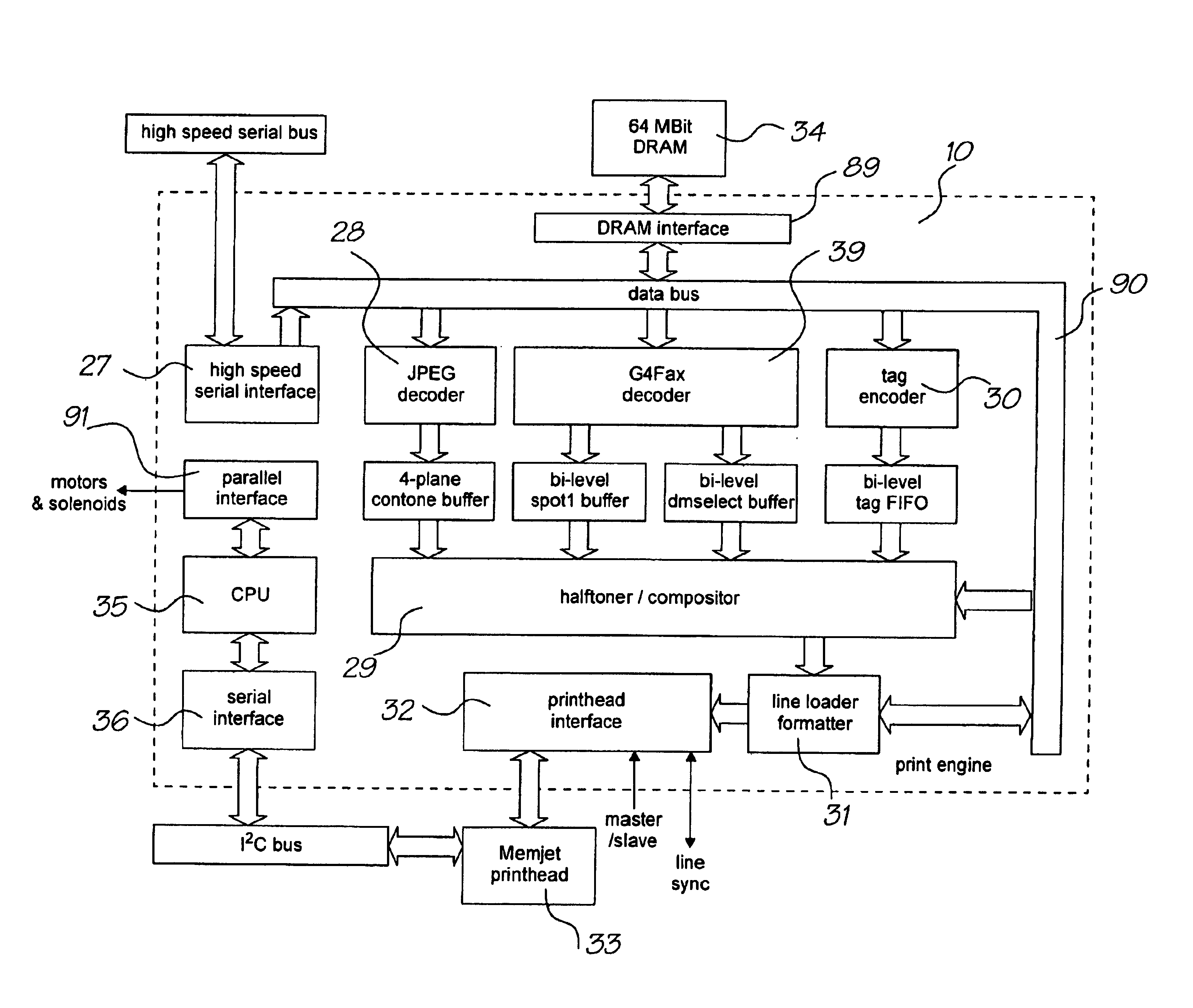
[0040]A typically 12 inch printhead width is controlled by one or more print engine / controllers (PECs), as described below, to allow full-bleed printing of both A4 and Letter pages. Six channels of colored ink are the expected maximum in the present printing environment, these being:[0041]CMY, for regular color printing.[0042]K, for black text and other black printing.[0043]IR (infrared), for tag-enabled applications.[0044]F (fixative), to enable printing at high speed.

[0045]Because the printer is to be capable of fast printing, a fixative will be required to enable the ink to dry before the next page has completed printing at higher speeds. Otherwise the pages might bleed on each other. In lower speed printing environments the fixative will not be required.

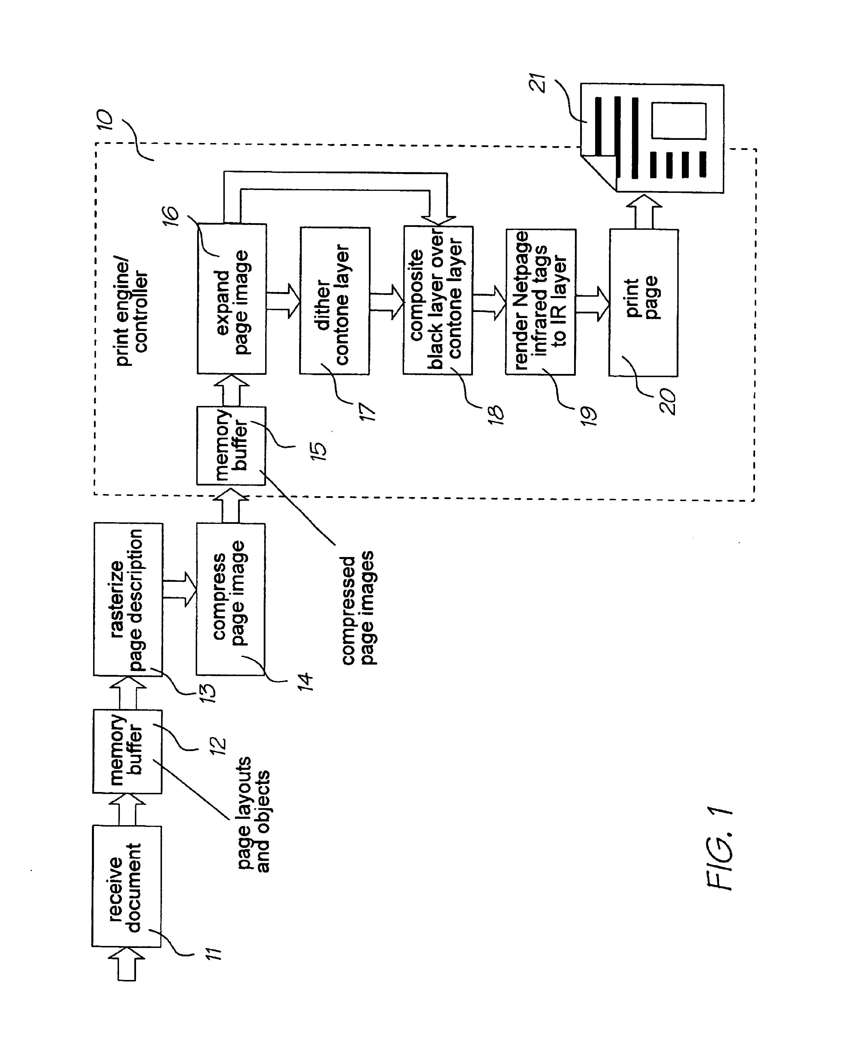
[0046]A PEC might be built in a single chip to interface with a printhead. It will contain four basic levels of functionality:[0047]receiving compressed pages via a serial interface such as IEEE 1394[0048]a print engine for produ...


PUM


Abstract

A printer with a multi-segment printhead has multiple engine / controllers (10) configured to be coupled with other engine / controllers to drive the printhead (33). The controllers each have an interface (27) at which to receive compressed page data. Image decoders (28, 88) decode compressed image planes image decoders to perform an expansion, in pipeline fashion, for the received compressed page data. A half-toner / compositer (29) composites respective strips of the decoded image planes and sends output to a printhead interface (32). A printhead interface (32) interfaces with the printhead. A synchronization signal generator (89,90) may output a synchronization signal that is used to synchronize print engine / controllers. One printhead interface (32) preferably acts as master generating the synchronization signal to synchronize all the print engine / controllers to drive the printhead at any one or more of higher speed, higher input resolution, higher outlet resolution or wider format. The half-toner / compositor (29) scales input image planes under control of a margin unit (57) set the print engine / controller to establish print data for a strip only of the image, the image being built from the respective strips from the multiple print engine / controllers.

Description

CROSS REFERENCE TO RELATED APPLICATION[0001]This is a Continuation Application of U.S. Ser. No. 09 / 607,985 filed on Jun. 30, 2000, all of which is herein incorporated by reference.FIELD OF THE INVENTION[0002]The invention relates to a print engine / controller adapted to work together with a number of print engine / controllers in driving a printhead and to a printhead driven by multiple print engine / controllers.BACKGROUND OF THE INVENTION[0003]In the prior art a single print engine / controller controls a single printhead. However this solution does not scale well for wider format printheads, for high resolution input images, or for faster printing. For wide format printheads the controller chip has to be made to run faster in order to print the same number of printlines, each of which is now longer. Or if the printhead is to run faster the print controller has to be run at a faster clock speed. Or if the input image has a higher resolution then the controller chip has to have more buffe...

Claims


Application Information

Patent Timeline
Patent Type & Authority Patents(United States)
IPC IPC(8): B41J2/01G06K15/02G06F13/00G06T1/20G06F3/12H04N1/405H04N1/21H04N1/64H04N1/413H04N1/52H04N1/50H04N1/387
CPCG06F3/1208G06F3/1213G06F3/1277G06F3/1282
Inventor WALMSLEY, SIMON ROBERTLAPSTUN, PAUL
Owner SILVERBROOK RES PTY LTD
Learn More