
Resistance assembly for hookstick operated switching assembly

a technology of resistance assembly and switch blade, which is applied in the direction of emergency protective circuit arrangement, air-break switch, hot stick switch, etc., can solve the problems of equipment damage, unintentional movement or so as to prevent accidental opening and closing of the switch, prevent accidental movement of the switch blade, and prevent accidental closing of the switch blade

Active Publication Date: 2005-09-20
HUBBELL INC
View PDF19 Cites 10 Cited by
  • Summary
  • Abstract
  • Description
  • Claims
  • Application Information

AI Technical Summary

Benefits of technology

[0010]A further objective of the present invention is to provide a resistance assembly to prevent accidental movement of the switch blades of the hookstick operated switch assembly.
[0011]A still further objective of the present invention is to provide a resistance member that prevents accidental closing of the switch blades of the hookstick operated switch assembly when in the opened position.
[0012]The foregoing objects are basically attained by providing a resistance assembly having a resistance member to prevent accidental movement of a hookstick operated switching assembly. A switch of the hookstick operated switching assembly is mounted on a base. The resistance member includes a lever connected to the switch to move the switch between opened and closed positions. A first end of a pin is connected to the lever. A roller is connected to a second end of the pin. The roller contacts the base when the lever rotates to move the switch between opened and closed positions, thereby preventing accidental opening and closing of the switch.

Problems solved by technology

High voltage overhead power switches are typically mounted well above ground and experience a variety of externally applied forces, such as weather, wild animals, vandalism, utility pole deformation, and vibration, which may cause a switch blade to move or close unintentionally.
Furthermore, if a switch blade moves close enough to a contact, flashover may occur.
Accidental closing of a switch blade may cause equipment damage, loss of electrical service and personnel injury.

Method used


Image

  • Resistance assembly for hookstick operated switching assembly
  • Resistance assembly for hookstick operated switching assembly
  • Resistance assembly for hookstick operated switching assembly

Examples


Embodiment Construction

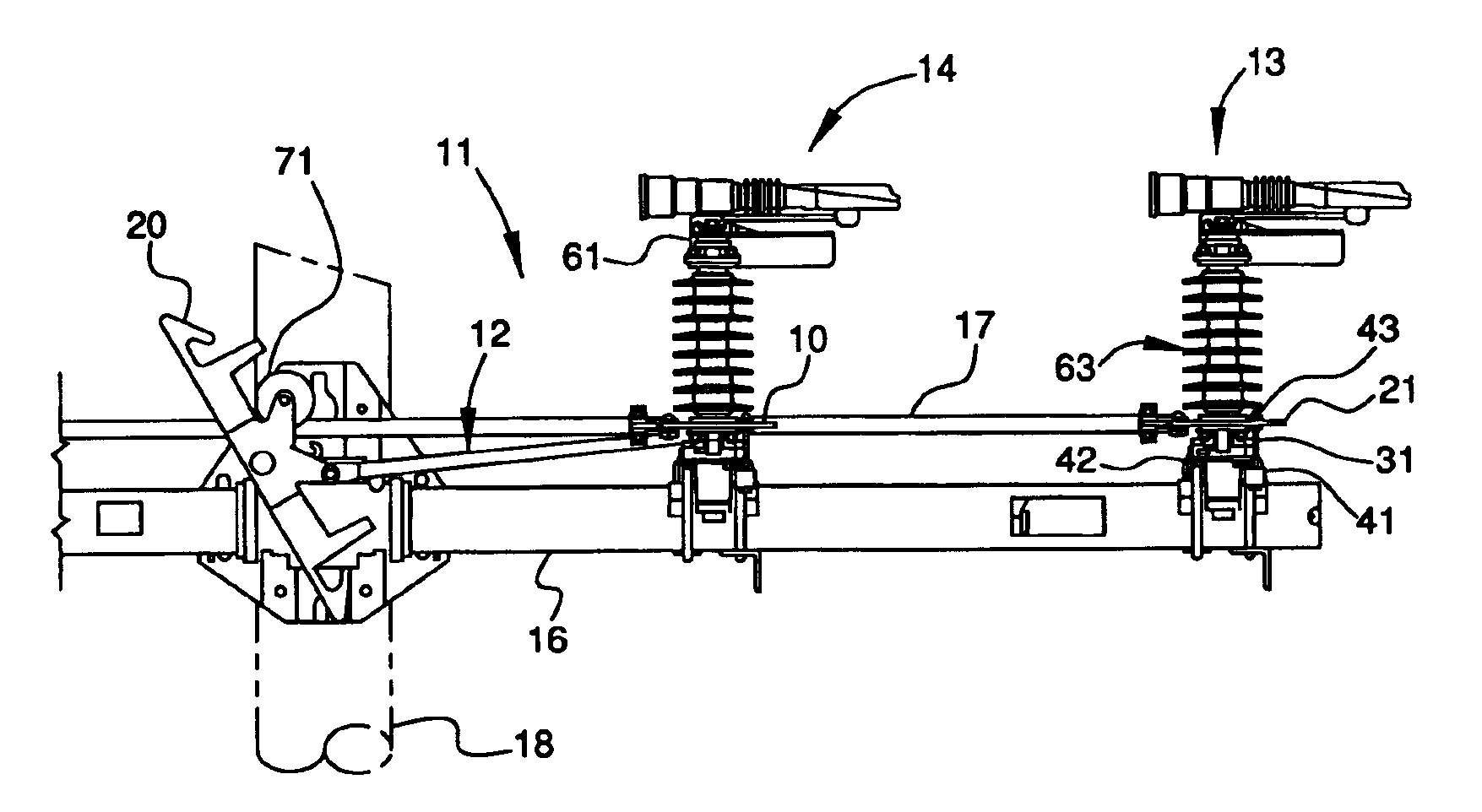
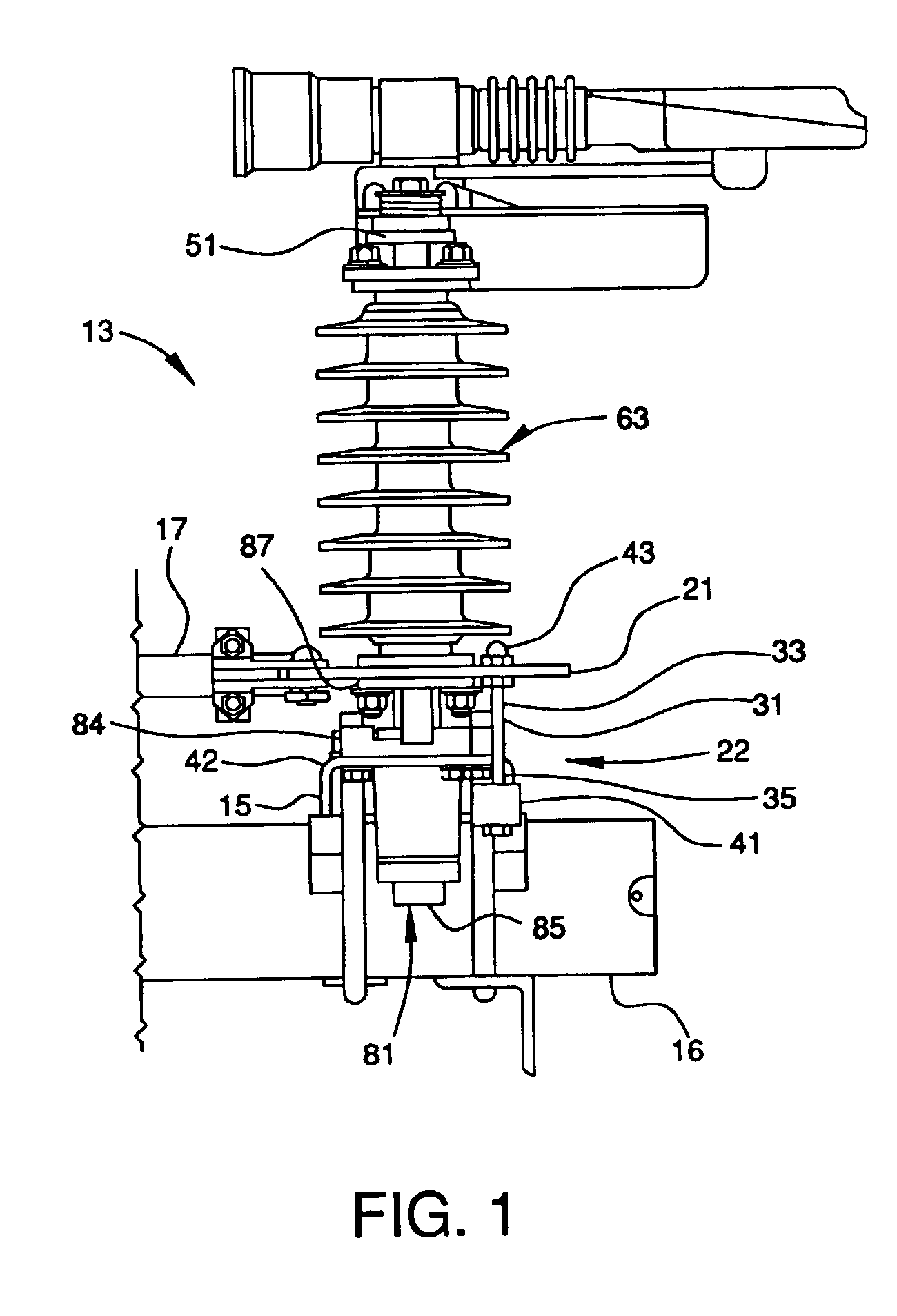
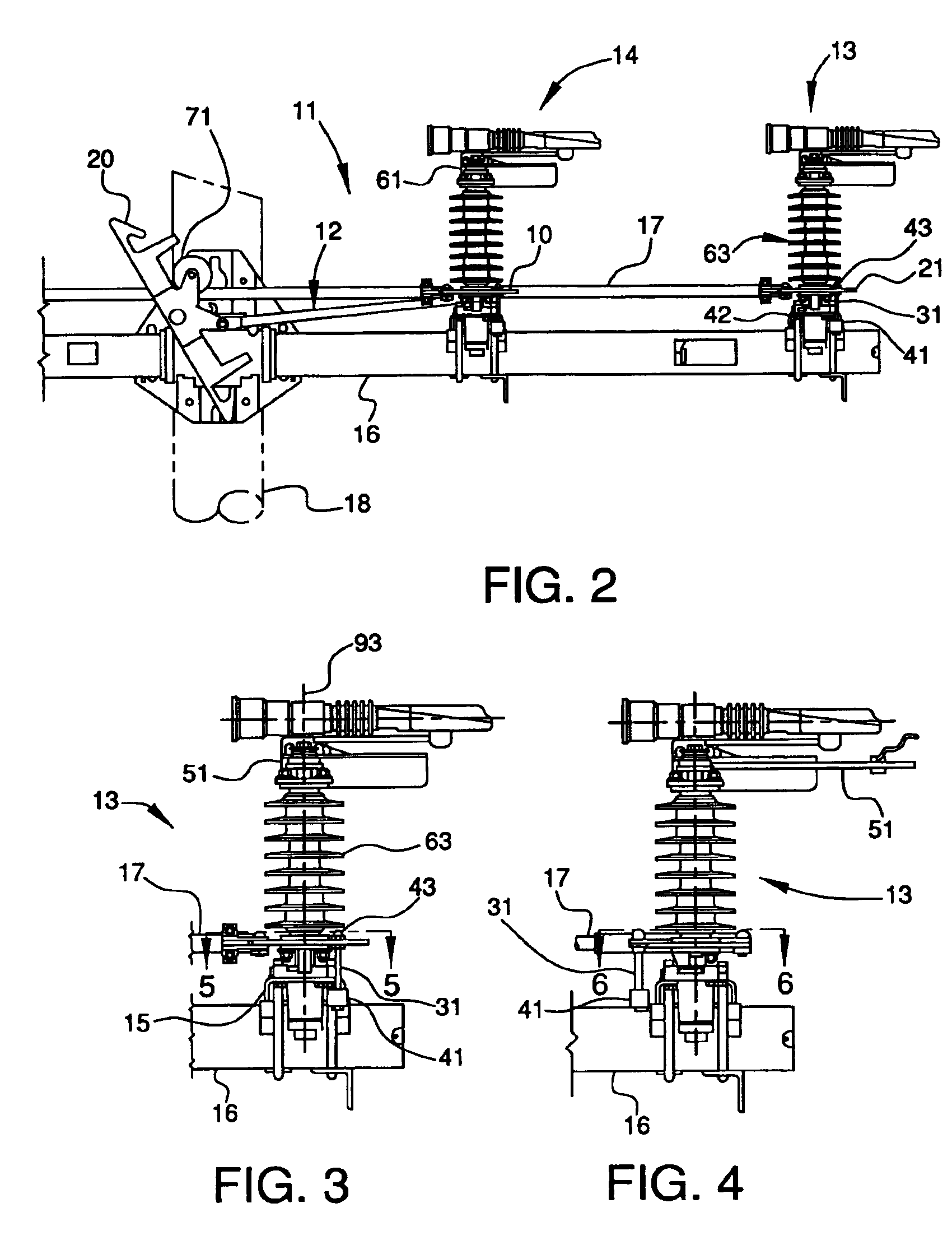
[0030]The present invention relates to a resistance assembly for a hookstick operated switching assembly 11 (FIG. 2), such as the group-operated switching assembly disclosed in U.S. Pat. No. 6,459,053 to Roberts and the hookstick operated switching assembly disclosed in U.S. Pat. No. 6,541,717 to Roberts, the subject matters of both are hereby incorporated by reference in their entirety.

[0031]Briefly described in the context of a three phase switch assembly, the present hookstick operated switching assembly 11 is made of three modular switch assemblies, two switch assemblies 13 and 14 being shown in FIG. 2. The switch assemblies are operated simultaneously by displacement of a rigid interphase shaft 17. The interphase shaft 17 is initially urged to move by pivotal, rigid linkages through at least one of the switch phase levers on a switch assembly 14 that is, in turn, pivotally and rigidly linked to an hookstick lever 20 that rotates between a closed position (FIG. 2) and an open po...


PUM


Abstract

A resistance assembly having a resistance member prevents accidental movement of a hookstick operated switching assembly. A switch assembly of the hookstick operated switching assembly is mounted on a base. The resistance member includes a lever connected to the switch assembly that moves the switch between opened and closed positions. A first end of a pin is connected to the lever. A resistance member is connected to a second end of the pin. The resistance member contacts the base when the lever rotates to move the switch assembly between open and closed positions, thereby preventing accidental opening and closing of the switch assembly.

Description

CROSS-REFERENCE TO RELATED APPLICATION[0001]This application claims the benefit under 35 U.S.C. § 119(e) of provisional patent application Ser. No. 60 / 432,646, filed Dec. 12, 2002, which is hereby incorporated by reference in its entirety.FIELD OF THE INVENTION[0002]The present invention relates to a resistance assembly for a hookstick operated switching assembly. More particularly, the present invention relates to a resistance member that prevents accidental closing of the switch blades of the hookstick operated switching assembly when the switch blades are in the open position. Still more particularly, the present invention relates to a pin and roller assembly that contacts a base of the hookstick operated switching assembly to resist movement of the switches from open to closed position until sufficient force is exerted to overcome the resistance.BACKGROUND OF THE INVENTION[0003]Overhead electric power distribution lines are supported on utility poles that may be 40-50 feet high....

Claims


Application Information

Patent Timeline
Patent Type & Authority Patents(United States)
IPC IPC(8): H01H31/00H01H9/20H01H9/22H01H9/54H01H21/54H02H7/26
CPCH01H31/006H01H9/223
Inventor ROBERTS, GERALD B.
Owner HUBBELL INC
Learn More