Method and apparatus for increasing track density by adapting write fault gate to position error signal as it varies from ID to OD

Inactive Publication Date: 2005-09-06
MAXTOR
View PDF12 Cites 33 Cited by
  • Summary
  • Abstract
  • Description
  • Claims
  • Application Information

AI Technical Summary

Benefits of technology

[0023]The present invention is directed to a method for increasing the capacity of a disk drive by increasing the track density for each disk in the drive.
[0025]The slope of the PES curve decreases across the stroke as the stroke moves from the OD towards the ID. The write fault gate thresholds for the tracks can be decreased in relation to the decrease of the slope, increasing the track density as the stroke approaches the ID, increasing the capacity of the drive.
[0027]By adjusting the write fault gate (WFG) threshold to the PES, a more uniform margin to encroachment failure is provided across the entire stroke of the actuator; i.e., prior art had more margin at the ID. WFG thresholds provide the limit as to how far a transducer can write off-track, so with equalized encroachment margin, tracks can be spaced closer together at the ID. In other words, the maximum WFG threshold will be made constant as a percent of track-spacing by increasing track-spacing density where the PES is low. This provides a net gain in capacity through servo track-writing of more tracks on the disk where the PES is low.

Problems solved by technology

Consequently, transducer positioning is not as accurate on track 318 as it would be on an ideal track.
As above mentioned, when a transducer moves off-track during a write operation, there is a chance that the transducer might inadvertently write data on or near an adjacent track, thus corrupting the data written on the adjacent track.
In addition, the data that is written off-track by the transducer may be difficult or impossible to read during a subsequent read operation on the present track due to its off-track position.
As can be appreciated, the greater the number of units that are left unused during the manufacturing process, the greater the overall manufacturing costs.
While the above described method of generating separate write fault gate values for each of the transducers in a disk drive permits matching transducers to a drive, enabling more drives to be certified for shipment, the write fault gate threshold values for the transducers are still limited by the minimum write fault gate threshold attributable to the position error at the worst case, i.e., at the outer diameter.

Method used


Image

  • Method and apparatus for increasing track density by adapting write fault gate to position error signal as it varies from ID to OD
  • Method and apparatus for increasing track density by adapting write fault gate to position error signal as it varies from ID to OD
  • Method and apparatus for increasing track density by adapting write fault gate to position error signal as it varies from ID to OD

Examples


Embodiment Construction

[0037]While this invention is susceptible of embodiments in many different forms, there are shown in the drawings and will herein be described in detail, preferred embodiments of the invention with the understanding that the present disclosure is to be considered as an exemplification of the principles of the invention and is not intended to limit the broad aspects of the invention to the embodiments illustrated.

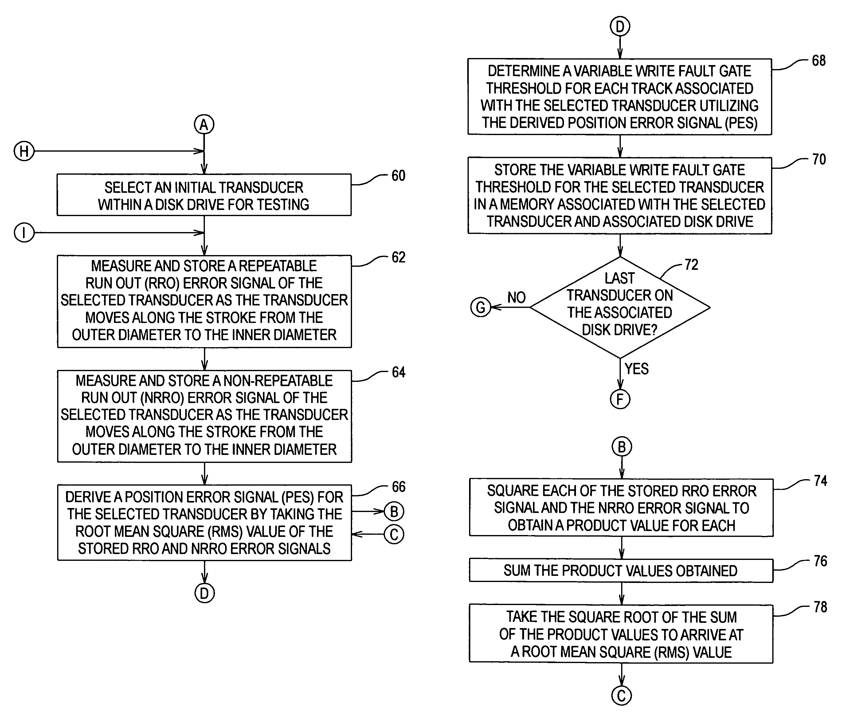
[0038]In conceiving of the present invention, the inventors have made a number of observations, some of which are listed below. Specifically, the inventors have recognized that track write width is a function of the write fault gate of that track with the write fault gate being a function of position error. Further, position error is a function of disk radius, decreasing as the radius approaches the inner diameter (ID) of the disk.

[0039]Additionally, the prior art uses steps of equal angle at the servo track writer which has the effect of increasing the track density at a ra...


PUM


Abstract

A disk drive utilizes a track dependent variable write fault gate for each of the transducers within the drive. By deriving a 3 sigma distribution across the repeatable run out (RRO) and the non-repeatable run out (NRRO), a position error signal (PES) is derived which varies in magnitude across the stroke of the transducers and which has a slope used to derive variable write fault gate thresholds for the tracks associated with each transducer. As the stroke of the transducer moves from the outer diameter (OD) to the inner diameter (ID), the magnitude of the write fault gate thresholds may be decreased relative to the PES, and track density and capacity may increase where PES and write fault gate thresholds are low. The invention thus maintains a constant hard error recovery margin across the stroke.

Description

[0001]Priority is claimed from U.S. Provisional Patent Application Ser. No. 60 / 246,341 filed Nov. 7, 2000 entitled “Method to Achieve High Track Density by Adapting the Write Fault Gate to the Position Error Signal as it Varies Across the Stroke from ID to OD,” which is incorporated by reference in its entirety.FIELD OF THE INVENTION[0002]The invention relates generally to data storage systems and, more particularly, to a method for increasing track density of the magnetic storage medium associated with the data storage system.BACKGROUND OF THE INVENTION[0003]FIG. 1 is a block diagram illustrating a disk drive 100 in accordance with one embodiment of the present invention. As illustrated, the disk drive 100 is coupled to an external host computer 102 that uses the disk drive 100 as a mass storage device. It should be appreciated that the blocks illustrated in FIG. 1 are functional in nature and do not necessarily represent discrete hardware elements. For example, in one approach, tw...

Claims


Application Information

Patent Timeline
IPC IPC(8): G11B5/596
CPCG11B5/59627G11B5/012G11B5/59688
Inventor MCNEIL, MICHAELMELROSE, THOMASMALANG, KEITH
Owner MAXTOR
Why Eureka
Try Eureka