
Method for reducing particle emissions containing carbon of diesel motors and corresponding system

a technology of diesel motors and carbon, applied in the direction of machines/engines, mechanical equipment, separation processes, etc., can solve the problems of substantial gas heating, so high burnout duration and power density, and achieve the effect of harmless emission reduction of diesel engine particles

Inactive Publication Date: 2005-09-06
CONTINENTAL AUTOMOTIVE GMBH
View PDF28 Cites 40 Cited by
  • Summary
  • Abstract
  • Description
  • Claims
  • Application Information

AI Technical Summary

Benefits of technology

[0024]Therefore, it is an object of the invention to provide a method and an associated system which can render the particle emissions from diesel engines harmless more effectively than has hitherto been possible.
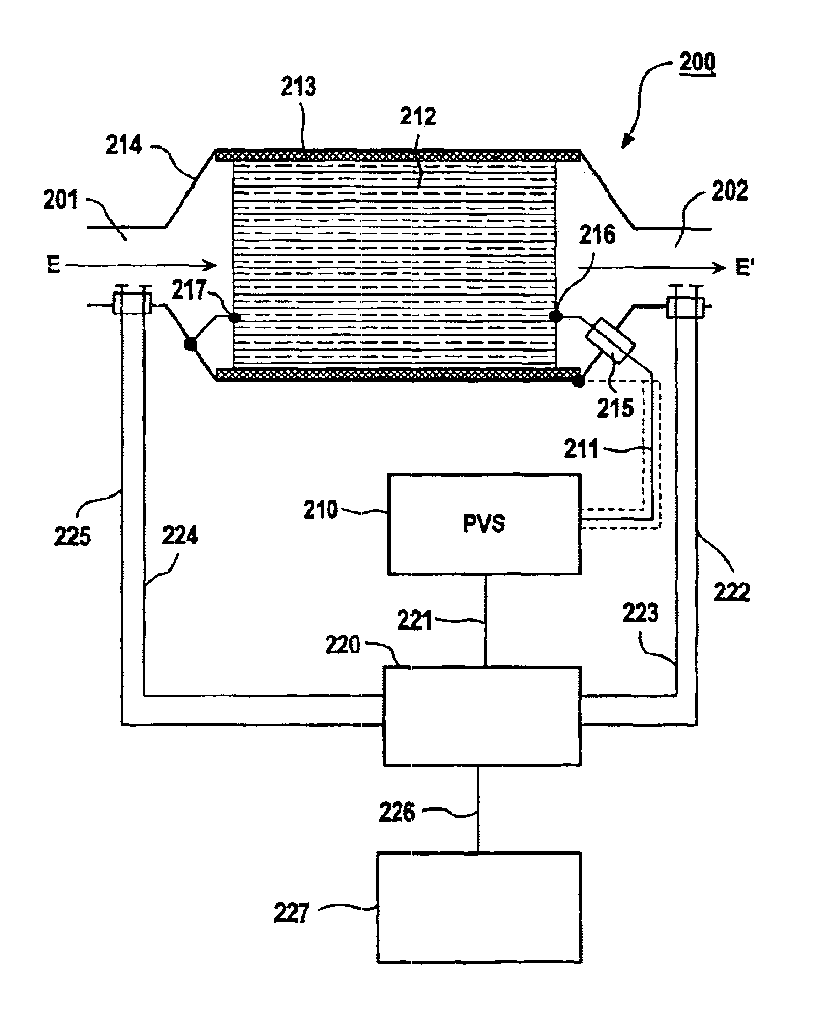
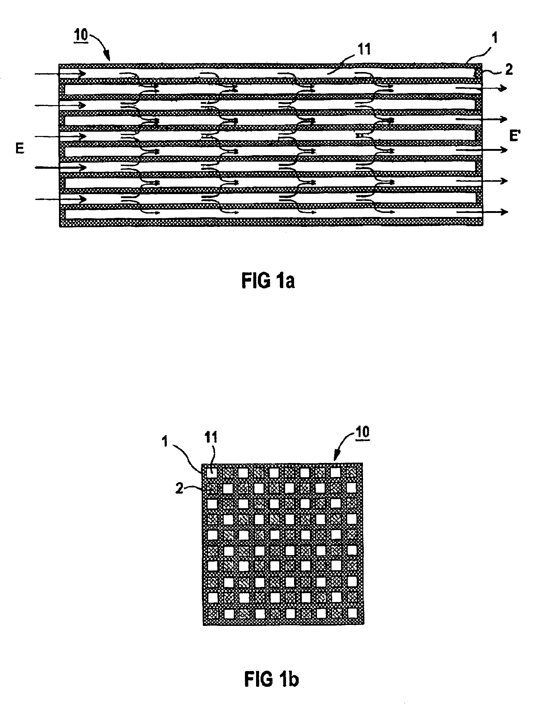
[0030]The invention proposes a method which combines the separation of particulates by ceramic particulate filters with the regeneration of the filters by non-thermal surface creeping discharges. Ceramic particulate filters are known to ensure a high level of separation efficiency of even fine particles. The surface creeping discharges allow the electrical energy in the immediate vicinity of the particulates separated out to be used to form oxidizing free radicals. As a result, there is a high probability of these free radicals reacting with the particulates and therefore also a high energy efficiency.
[0031]The electrode structures required for a method according to the invention can (a) both be embedded in the filter walls, (b) be applied to opposite sides of the filter walls as surface electrodes, (c) alternately be formed as embedded electrodes and as surface electrodes. This allows a low flow resistance to be achieved with a compact structure of the filter element.
[0032]According to one aspect of the invention, the filter walls are formed of a finely porous ceramic material of low electrical conductivity. As a result, the filter wall acts as a dielectric barrier which prevents a direct flow of current. Therefore, it is proposed to operate with a high voltage which changes over the course of time, either in the form of an alternating voltage or in the form of a pulsed voltage which repeats itself over the course of time. The mean electrical power converted into surface creeping discharges results from the product Edis x f of electrical energy Edis dissipated per pulse or per period and pulse repetition rate or frequency f. The dissipated energy Edis increases as the voltage amplitude U0 rises. The pulsed voltage is characterized in that the duration of the voltage pulse is short compared to the period given by the pulse repetition frequency. As a result, the energy is introduced in targeted fashion into the generation of non-thermal surface gas discharges, and there is no excessive dissipation of electrical energy as a result of the residual conductivity of the filter ceramic and as a result of conductive particulate deposits on the filter.
[0034]The plasma regeneration of the filter may take place continuously. The mean plasma power required is represented by a function which drops as the filter temperature rises and rises as the emission of particulates rises. As an alternative to particulate emission, it is also possible for the exhaust-gas back pressure to be used as an input variable for controlling the mean plasma power. The advantage of this method lies in the fact that the exhaust-gas back pressure can be continuously kept at a low level. As a result, the increased fuel consumption which may occur in internal combustion engines as a result of a rising exhaust-gas back pressure is substantially avoided. On the other hand, this does result in an increased outlay on energy for operation of the plasma. The energy content of hydrocarbons and particulates is in practice not used for the regeneration.
[0039]Furthermore, by selecting the catalytic doping of the filter material, it is possible to enable the plasma-induced catalytic reduction of nitrogen oxides by hydrocarbon-containing reducing agents to take place in the particulate filter itself. In both cases, the control strategy for plasma operation should additionally be matched to the requirements of the NOx reduction.

Problems solved by technology

At atmospheric pressure, surface creeping discharges often burn as sparks in which, however, the burning duration and power density are so high that substantial gas heating still occurs.

Method used


Image

  • Method for reducing particle emissions containing carbon of diesel motors and corresponding system
  • Method for reducing particle emissions containing carbon of diesel motors and corresponding system
  • Method for reducing particle emissions containing carbon of diesel motors and corresponding system

Examples


Embodiment Construction

[0049]Reference will now be made in detail to the preferred embodiments of the present invention, examples of which are illustrated in the accompanying drawings, wherein like reference symbols refer to like elements throughout. Some of the figures are described jointly.

[0050]The method described below for reducing the levels of particulate emissions is based on the following assumptions:[0051]To ensure efficient breakdown by oxidation, the particulates have to be collected on surfaces. This is most reliably ensured by the particulate filters which are known .[0052]Oxidation which is effective even at low temperature without the addition of catalytic additives can only be achieved by oxidizing free radicals which are formed in the immediate vicinity of the surface. This can be induced with a good level of efficiency by electron collisions for example with oxygen in a non-thermal plasma:

O2+e→O+O+e  (1)[0053] The oxygen free radicals react with the carbon surface C(s) and in the proces...


PUM


Abstract

Exhaust gas amitted from a diesel engine flows through a ceramic soot filter in which particles contained in the exhaust are deposited and oxidized to regenerate the filter. The filter is regenerated by non-thermal, electric surface creeping discharge on filter surfaces covered with particles. In addition, nitrogen oxides may be reduced by selective catalytic reduction. The system is designed to ensure operation reliability and environmental compatibility.

Description

CROSS REFERENCE TO RELATED APPLICATIONS[0001]This application is based on and hereby claims priority to German Patent Application Nos. 100 57 862.4 and 101 30 163.4 filed on November 2000 and Jun. 22, 2001, respectively, the contents of which are hereby incorporated by reference.BACKGROUND OF THE INVENTION[0002]1. Field of the Invention[0003]The invention relates to a method for reducing the level of carbon-containing particle emissions from diesel engines, in which the exhaust gas emitted by the engine flows through a filter, the particles contained in the exhaust gas are separated out at filter surfaces, and in which the particles which have been separated out are oxidized in order for the filter to be regenerated. In addition, the invention also relates to an associated system for carrying out the method, having a ceramic particulate filter and means for oxidizing the particles which are separated out at the ceramic filter.[0004]2. Description of the Related Art[0005]Recent studi...

Claims


Application Information

Patent Timeline
Patent Type & Authority Patents(United States)
IPC IPC(8): B01D53/92F01N3/023F01N3/027F01N3/022F01N3/035F01N3/20F01N3/02B01D53/94F01N3/24F01N3/28
CPCB01D53/92F01N3/0222F01N3/0275F01N3/035F01N3/20F01N2240/28F01N2570/14Y02T10/24Y02A50/20Y02T10/12
Inventor BIRCKIGT, RUDOLFHAMMER, THOMASKISHIMOTO, TETSUO
Owner CONTINENTAL AUTOMOTIVE GMBH
Learn More