
System and method for linear object reallocation in place

a reallocation and object technology, applied in the field of memory devices, can solve the problems of data cannot be simply overwritten, data is only limited to voice communication, and the amount of memory consumed by data such as voice information and image files can be considerable, so as to avoid unnecessary flash memory write cycles and save time

Inactive Publication Date: 2005-08-30
MICRON TECH INC
View PDF20 Cites 34 Cited by
  • Summary
  • Abstract
  • Description
  • Claims
  • Application Information

AI Technical Summary

Benefits of technology

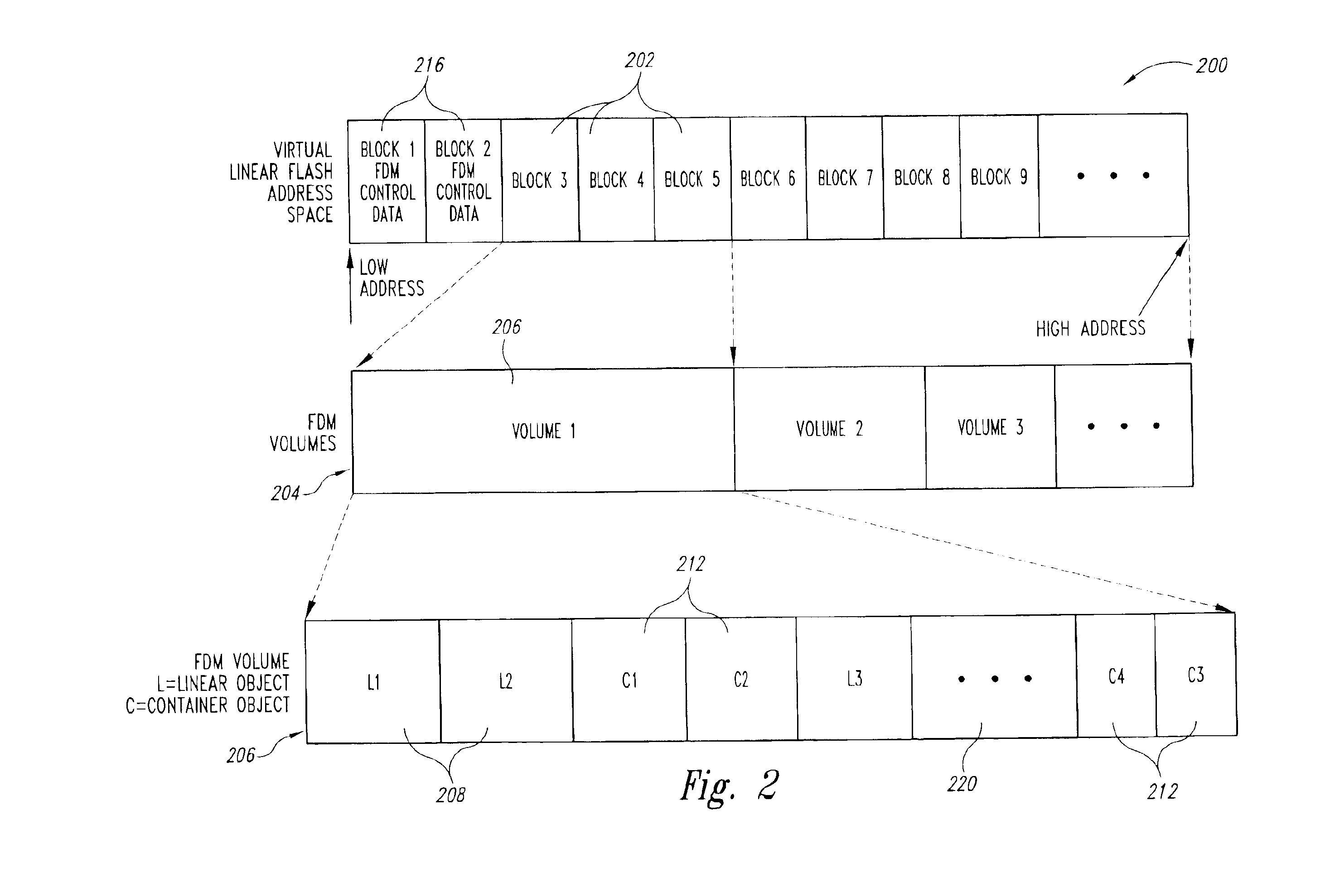
[0013]The present invention is directed to management of linear objects. In updating a linear object in a flash memory device with a revised linear object of the same size, the present invention overwrites the original linear object in the same memory space as the original version. Updating the data requires erasing and writing of blocks of flash memory cells where the linear object is stored, but requires no erasing or rewriting of tables in which that linear object is stored, saving time and avoiding the unnecessary consumption of flash memory write cycles.

Problems solved by technology

At one time, cellular phones were only limited to voice communication.
Additionally, the amount of memory consumed by data such as voice information and image files can be considerable, spanning multiple blocks of flash memory.
For example, because of the floating gate structure of conventional flash memory cells, data cannot be simply overwritten.
Additionally, erasing the entire block is a problem, however, in the case where another portion of the memory cells of the block do not need to be updated.
Another issue related to flash, and other floating gate memory devices, is that these memory cells have a limited life-cycle where repeated cycles of erasing and programming degrade memory cell performance.
Eventually, the cell performance is degraded to such a degree that the memory cell can no longer be used to store data.
Conventional memory management software has limitations in the area of data management.
Consequently, if at a later time a different partitioning between code and data is desired, the ranges defined for the two types of data cannot be modified unless software is recompiled.
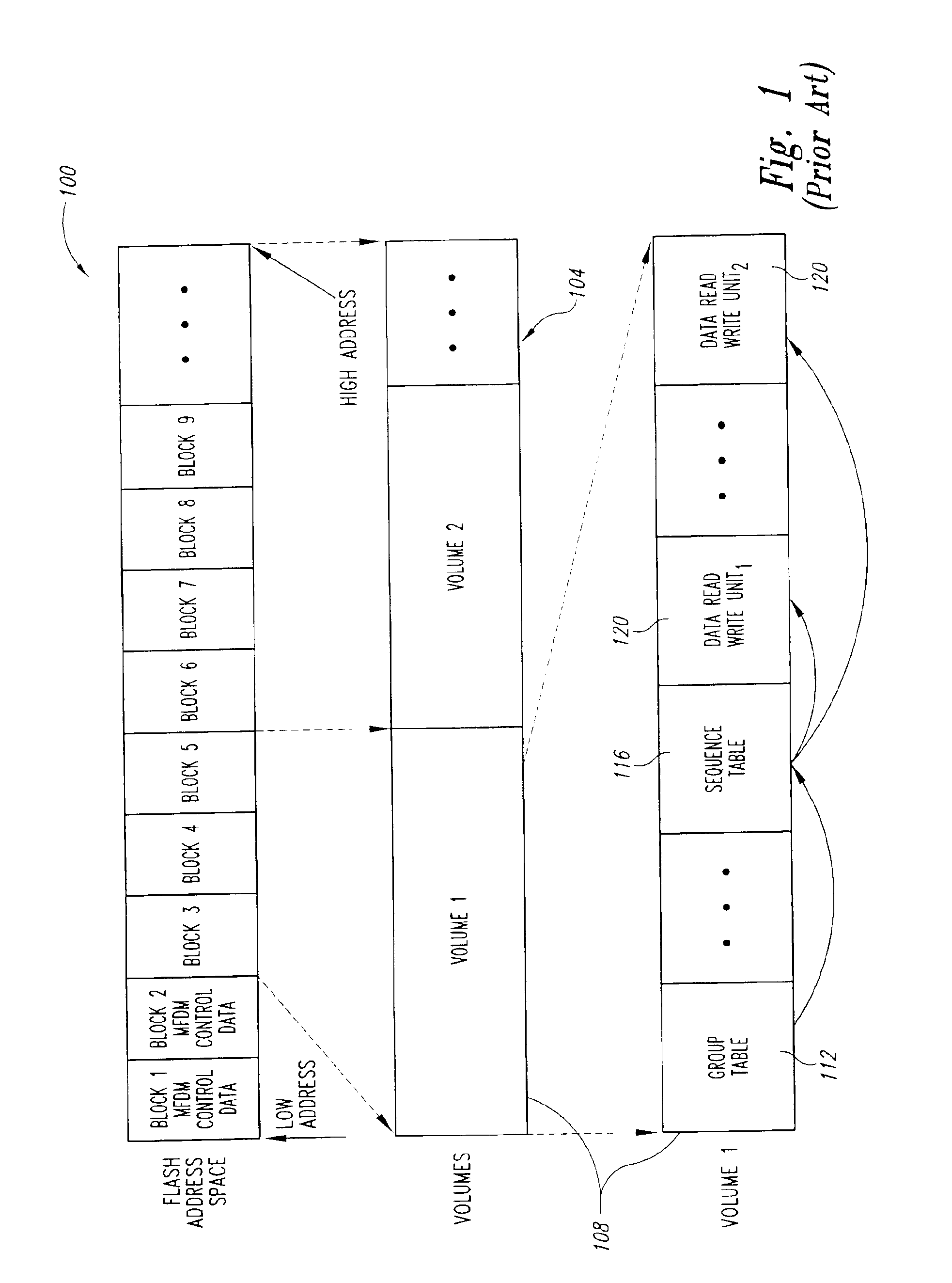
Unfortunately, the hierarchical arrangement shown in FIG. 1 can result in appreciable consumption of both time and useful erase / write cycles.
Having to rewrite not only the data read / write units 120, but also two levels of tables is both time consuming and also consumes the useful life of the flash memory cells by necessitating more erase and write cycles for both the flash blocks where the data are stored and where the indices are stored.
Second, the manner in which new data or index elements are created under conventional flash memory management processes leave something to be desired in terms of data recovery.
Accordingly, if a user of the device in which the flash memory device is used changes his or her mind about the change, the original data will have been erased or otherwise no longer available to restore the original data.
In addition, if the conventional process continually uses predefined blocks of flash memory for temporary storage of such data, the useful life of the flash memory cells in those blocks may be exhausted before other cells in the same flash memory device, therefore hastening the end of the useful life of that flash memory device.

Method used


Image

  • System and method for linear object reallocation in place
  • System and method for linear object reallocation in place
  • System and method for linear object reallocation in place

Examples


Embodiment Construction

[0022]Embodiments of the present invention are directed to a memory management system and method that improves the process of changing or updating linear data segments, and also provides for an efficient manner of undoing these changes or updates. In the following detailed description of exemplary embodiments of the invention, reference is made to the accompanying drawings, which form a part hereof, and in which are shown, by way of illustration, specific exemplary embodiments in which the invention may be practiced. These embodiments are described in sufficient detail to enable those skilled in the art to practice the invention. However, it will be clear to one skilled in the art that the invention may be practiced without these particular details. Other embodiments may be utilized and modifications may be made without departing from the spirit or scope of the present invention. The following detailed description is, therefore, not to be taken in a limiting sense, and the scope of ...


PUM


Abstract

A system and method for replacing an original linear object with an updated linear object. In a flash memory or other memory device storing groups of data objects, in replacing a linear object with an updated linear object of the same size, the present invention overwrites the original linear object in the same memory space as the original version. As a result, updating the data requires erasing and writing of the block of flash memory cells where the data object is stored. A copy of the original linear object is stored so that the original version of the linear object is available for undoing the update and / or facilitating recovery if the updated linear object becomes corrupted.

Description

TECHNICAL FIELD[0001]The present invention relates to semiconductor memory devices. More particularly, the present invention relates to improving data management in semiconductor memory devices, such as flash memory devices.BACKGROUND OF THE INVENTION[0002]Non-volatile memory is a type of memory that can retain data and information even when power is not applied. An example of non-volatile memory that is being used in a variety of applications, such as cellular phone technology, is “flash memory.” Flash memory is a form of electrically erasable programmable read-only memory (EEPROM), where data can be written in bytes and erased in blocks of memory. The blocks of memory typically range from 8 kBytes to 1 MByte in size. The cell density of flash memory devices can be very high, often as high as conventional dynamic random access memory (DRAM) cells, since in conventional flash memory a single floating gate structure is used for each memory cell. Flash memory devices also have relativ...

Claims


Application Information

Patent Timeline
Patent Type & Authority Patents(United States)
IPC IPC(8): G06F12/02G06F12/00G06F9/445
CPCG06F8/665G06F12/0246G06F8/654
Inventor LOUIE, ROGERWONG, WANMO
Owner MICRON TECH INC
Learn More