
Selective deposition modeling build style providing enhanced dimensional accuracy

a technology build style, applied in the field of selective deposition modeling, can solve the problems of shortening the time to develop prototype parts, sdm systems, and limited number of parts produced in rapid manufacturing processes, and achieves less build material, less build material, and improved dimensional accuracy.

Inactive Publication Date: 2005-08-30
3D SYST INC
View PDF23 Cites 141 Cited by
  • Summary
  • Abstract
  • Description
  • Claims
  • Application Information

AI Technical Summary

Benefits of technology

[0015]The objects formed according to the present invention exhibit enhanced dimensional accuracy compared to solid objects formed by SDM and are well suited for use as sacrificial patterns in investment

Problems solved by technology

For instance, SFF technologies dramatically shorten the time to develop prototype parts and can produce limited numbers of parts in rapid manufacturing processes.
This is generally due to the use of relatively low cost dispensing devices employed in SDM systems such as ink jet print heads, instead of the expensive lasers and scanning components used in stereolithography systems.
However, SDM systems have some disadvantages.
Because most materials used in SDM inherently shrink as they solidify, the solid three-dimensional objects are subjected to non-linear distortion.
Undesirably, this non-linear distortion can cause, for example, flat planar surfaces to bow or distort as the object cools down to ambient temperatures.
In contrast to linear shrinkage, with occurs in all three dimensions and can be compensated for with shrink compensation factors, this non-linear distortion generally cannot be compensated for since it is dependent on the geometry of the object and the inherently non-uniform cooling rate of the object.
Thus, solid objects formed by SDM are not well suited in applications where high dimensional accuracy is needed; for example, such as in investment casting where the object is utilized as the sacrificial pattern for forming the final cast part.
Thus, this build style is generally not suitable for use in SDM applications utilizing a single phase change material.
However, forming the tetrahedron structure by SDM is not possible unless a support structure is formed to support the three non-vertically oriented legs of each tetrahedron which also adds unnecessary complexity to the build process.
Thus, this build style is also generally not suitable for use in SDM.

Method used


Image

  • Selective deposition modeling build style providing enhanced dimensional accuracy
  • Selective deposition modeling build style providing enhanced dimensional accuracy
  • Selective deposition modeling build style providing enhanced dimensional accuracy

Examples


Embodiment Construction

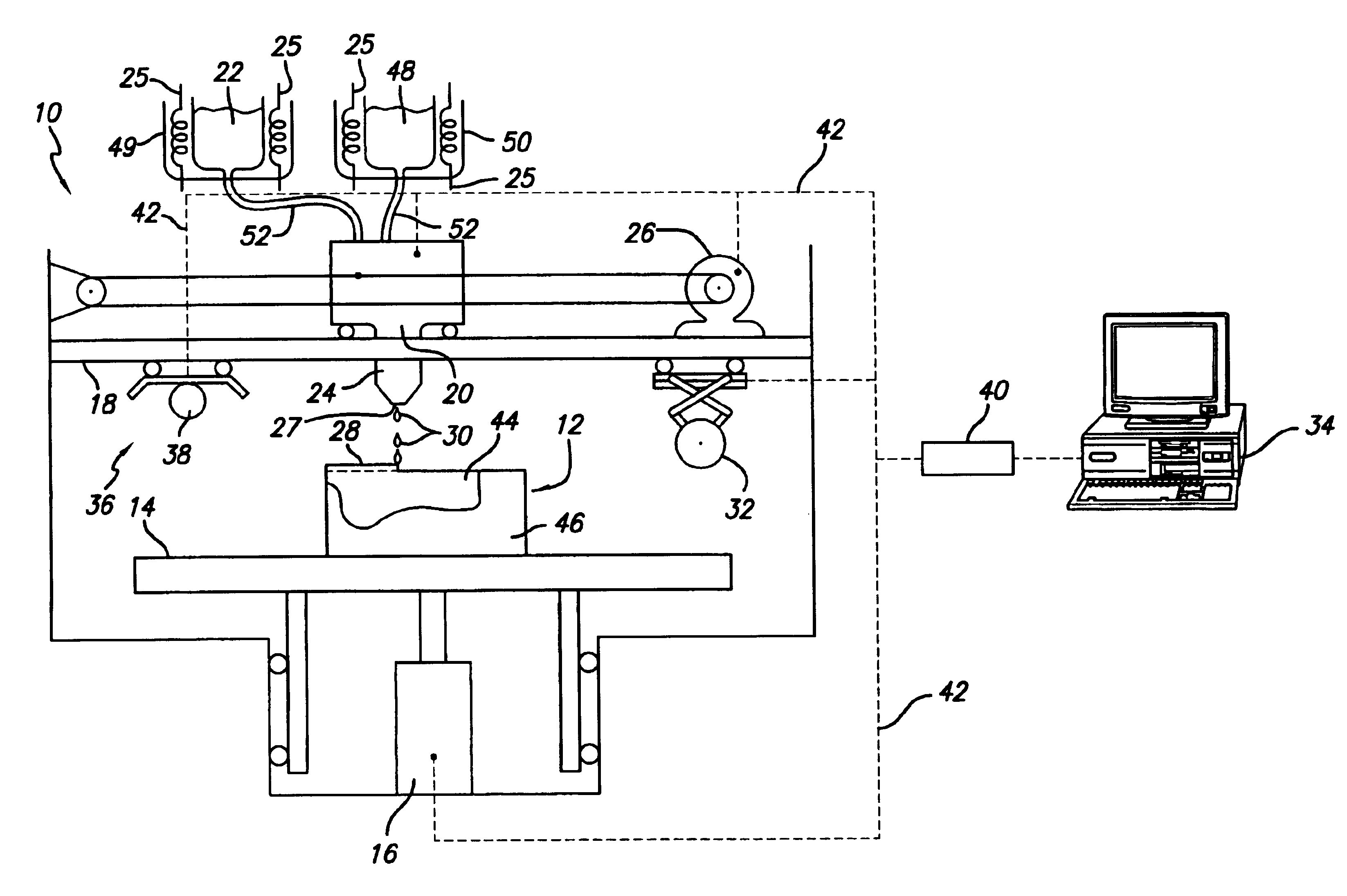
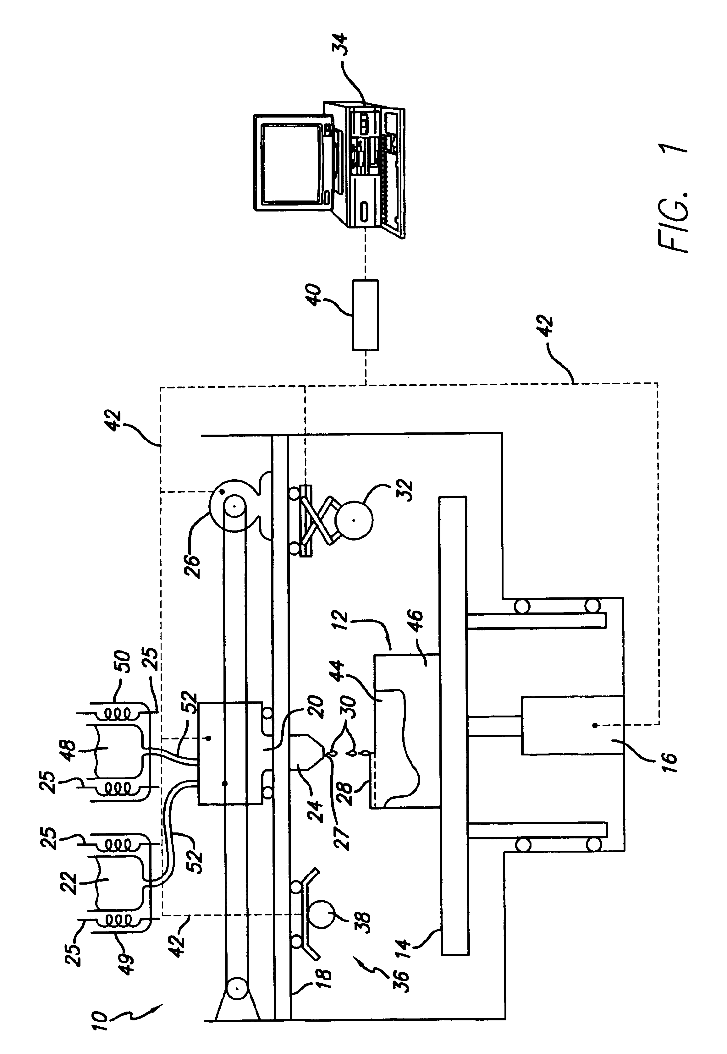
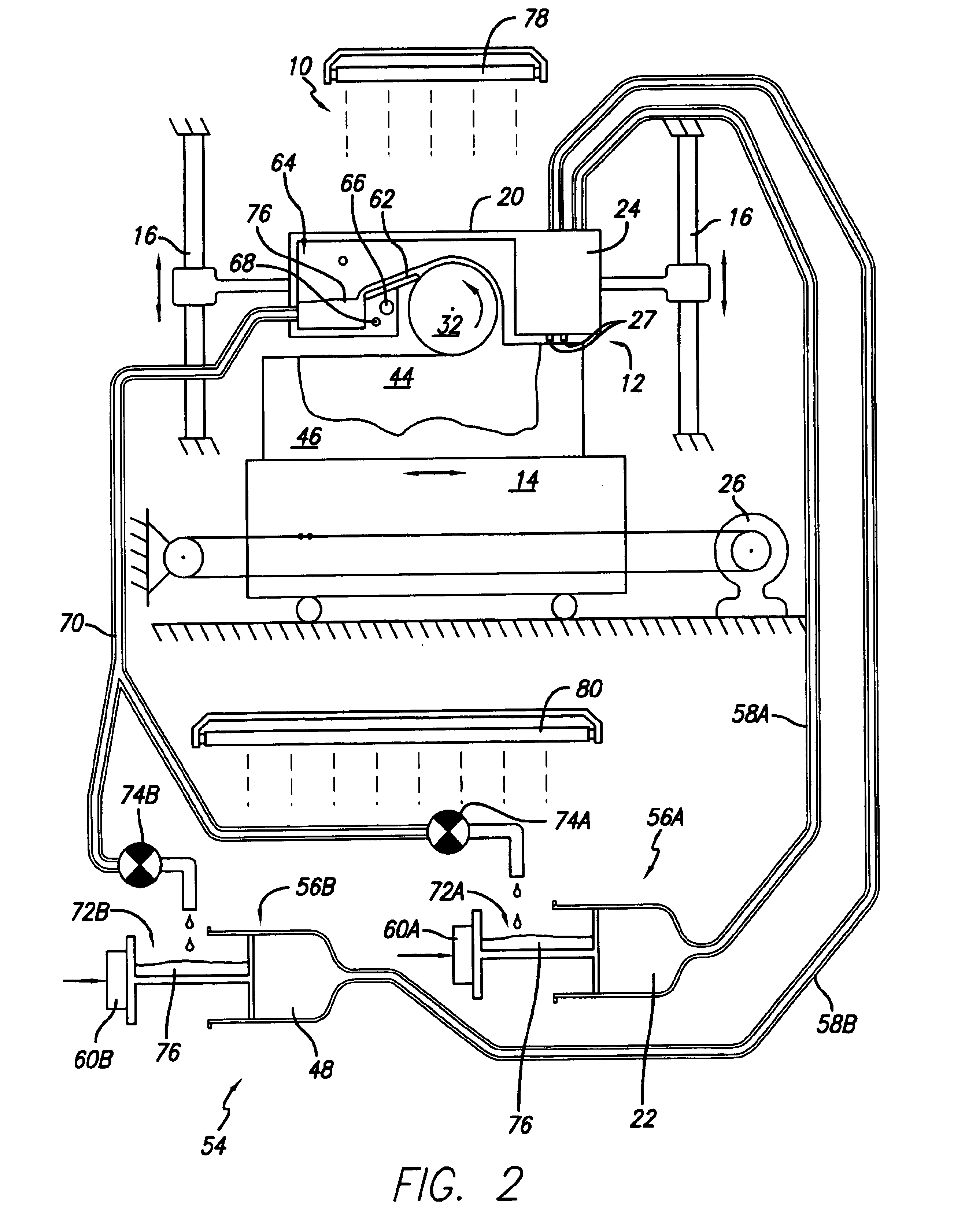
[0027]While the present invention is applicable to all SDM techniques, the invention will be described with respect to an SDM technique utilizing an ink jet print head dispensing phase change materials. However, it is to be appreciated that the present invention can be implemented with any SDM technique utilizing a wide variety of materials. For example, SDM techniques that extrude a thermoplastic build material may be used to practice the present invention. In addition, SDM techniques that dispense a photopolymer material, such as the DI 7090 Clear Coat material manufactured by Marabuwerke GmbH & Co., of Tamm, Germany, may also be used.

[0028]As used herein, the term “a flowable state” of a build material is a state wherein the material is unable to resist shear stresses that are induced by a dispensing device, such as those induced by an ink jet print head when dispensing the material, causing the material to move or flow. Preferably the flowable state of the build material is a li...


PUM

PropertyMeasurementUnit
Temperatureaaaaaaaaaa
Lattice constantaaaaaaaaaa
Shrinkageaaaaaaaaaa

Abstract

A method of forming a three-dimensional object in a layerwise manner is disclosed. The object is formed in a manner-that substantially prevents non-uniform distortion to occur during the layerwise build process as the build material forming the object solidifies and shrinks. The formed object comprises an outer surface defined by a shell structure and an internal lattice structure residing within the internal volume of the object. The object may be formed by any selective deposition modeling apparatus from a wide variety of materials.

Description

BACKGROUND OF THE INVENTION[0001]1. Field of the Invention.[0002]The invention relates in general to selective deposition modeling, and in particular to a method of dispensing a build material to form a three-dimensional object having enhanced dimensional accuracy. The enhanced dimensional accuracy of the three-dimensional objects formed make them useful as sacrificial patterns in investment casting processes or as dimensionally improved rapid prototypes.[0003]2. Description of the Prior Art.[0004]Recently, several new technologies have been developed for the rapid creation of models, prototypes, and parts for limited run manufacturing. These new technologies are generally called Solid Freeform Fabrication techniques, and are herein referred to as “SFF.” Some SFF techniques include stereolithography, selective deposition modeling, laminated object manufacturing, selective phase area deposition, multi-phase jet solidification, ballistic particle manufacturing, fused deposition modeli...

Claims


Application Information

Patent Timeline
IPC IPC(8): B29C41/08B28B1/14B28B1/00B28B17/00B29C41/36B29C41/48B29C67/00
CPCB28B1/00B28B1/001B28B17/0081B29C41/36B29C41/48B29C67/0059B29C67/0092B29C64/112B29C64/40B33Y10/00B33Y40/20
Inventor CRAWFORD, CLARK W.
Owner 3D SYST INC
Learn More