
Borehole retention device

a technology of retention device and borehole, which is applied in the direction of borehole/well accessories, drilling pipes, drilling rods, etc., can solve the problems of packerfeet being blown off the tractor, major well problems, and ineffective projections or ribs

Inactive Publication Date: 2005-08-30
HALLIBURTON ENERGY SERVICES INC
View PDF43 Cites 43 Cited by
  • Summary
  • Abstract
  • Description
  • Claims
  • Application Information

AI Technical Summary

Benefits of technology

[0013]The preferred embodiment of the present invention provides a larger expansion ratio and a more effective fluid flow-through area whether in the expanded or contracted position. A further advantage of the present invention is the use of an efficient, reliable and less expensive downhole umbilical propulsion system and survey system for accurate directional drilling.

Problems solved by technology

Such externally fluted anchors will sometimes bury themselves in soft formations and completely close off all flow channels causing major well problems.
These longitudinal projections or ribs are not effective in soft formations because upon expansion of the packerfeet, the ribs penetrate and bury in the soft earth formation causing the flutes to become packed off with earth and closing the return flow path through the annulus for the cuttings and return fluid.
Blockage also causes the packerfeet to be blown off the tractor due to the hydraulic pressure through the annulus.
Another deficiency of prior art packerfeet is that they are made of an elastomeric, stretchable material such that upon expansion, the packerfeet balloon and stretch to engage the borehole wall.
Another deficiency of the prior art packerfeet is that the amount of radial expansion is small.
This is due to the limit that the reinforcing fabric which is embedded in the elastomer can expand to.
Other packerfeet are limited to expanding the packerfeet the radial distance between the propulsion system mandrel and the wall of the borehole.
Single wedges reduces the camming area for camming the packerfeet into engagement with the borehole wall creating high stresses on the carrring surfaces.

Method used


Image

  • Borehole retention device
  • Borehole retention device
  • Borehole retention device

Examples


Embodiment Construction

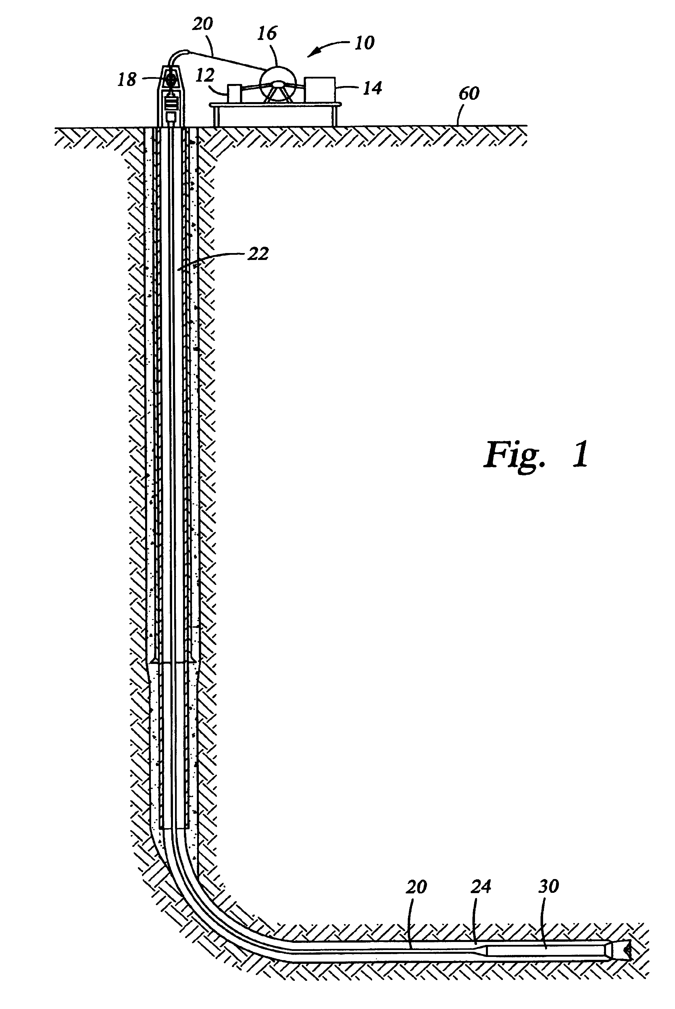
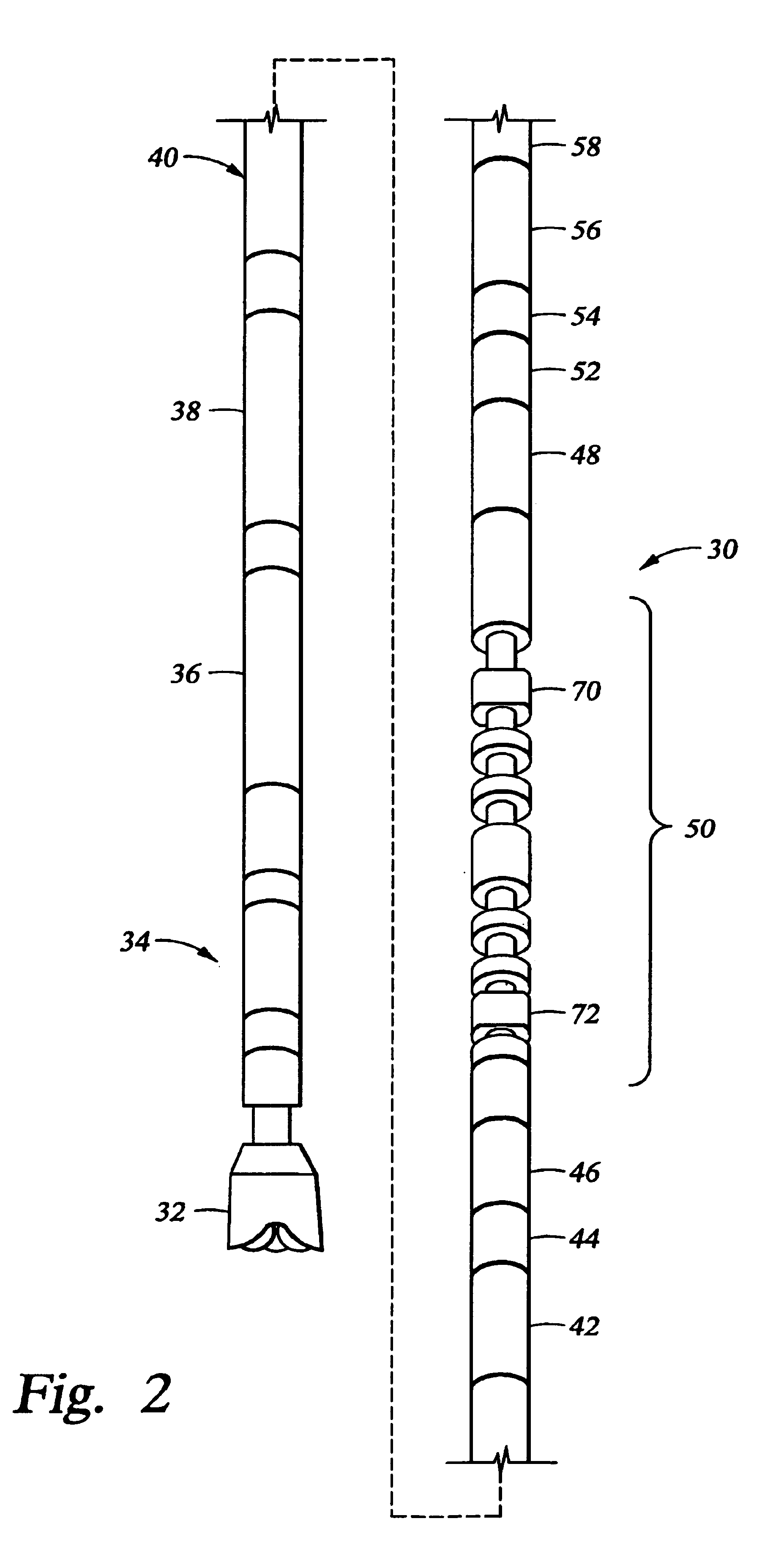
[0034]The present invention relates to methods and apparatus for anchoring a well tool in a well. The present invention is susceptible to embodiments of different forms. There are shown in the drawings, and herein will be described in detail, specific embodiments of the present invention with the understanding that the present disclosure is to be considered an exemplification of the principles of the invention, and is not intended to limit the invention to that illustrated and described herein.

[0035]In particular, various embodiments of the present invention provide a number of different constructions and methods of operation of the traction or retention module, each of which may be used to anchor a well tool in a borehole, casing, or pipe for a well including a new borehole, an extended reach borehole, extending an existing borehole, a sidetracked borehole, a deviated borehole, enlarging a existing borehole, reaming an existing borehole, and other types of boreholes for drilling an...


PUM


Abstract

A borehole retention assembly for anchoring a well tool within a wellbore including a gripping assembly and an actuation assembly. The gripping assembly includes expandable members such that upon expanding the expandable members, the gripping assembly engages the wall of the borehole. The gripping assembly includes a pair of expandable members and a medial member, the members having cooperating tapered surfaces therebetween such that upon the actuation assembly contracting the gripping assembly, the expandable members are cammed outwardly against the borehole wall. The gripping assembly is mounted on a mandrel enabling them to resist rotational and axial forces on the well tool. When engaged, space is provided on each side of the borehole retention assembly such that annular flow is permitted therearound.

Description

CROSS-REFERENCE TO RELATED APPLICATION[0001]The present application claims the benefit of 35 U.S.C. 119 of U.S. provisional application Ser. No. 60 / 201,353, filed May 2, 2000 and entitled Borehole Retention Device, hereby incorporated herein by reference in its entirety.BACKGROUND OF THE INVENTION[0002]The present invention relates to anchors or traction modules for thrust loads imparted by well tools, such as a thruster or tractor used in an assembly for performing a downhole operation in a well and more particularly to packer feet on a tractor in a bottom hole assembly, disposed on an umbilical, with a power section for rotating a bit while the tractor moves the bottom hole assembly within the well.[0003]In the course of drilling and completing oil and gas wells, it is sometimes desirable to set an anchor in closed or open hole to serve as a reaction point for various thrust forces imparted by operating tools. Expanding anchors, very much like packers, usually are fluted around th...

Claims


Application Information

Patent Timeline
IPC IPC(8): E21B17/10E21B17/00E21B23/08E21B23/00E21B4/18E21B4/00
CPCE21B4/18E21B17/1021E21B23/08E21B2023/008E21B23/001
Inventor KUSMER, DANIEL P.
Owner HALLIBURTON ENERGY SERVICES INC
Learn More