Exposure Head and Image Forming Device

Inactive Publication Date: 2010-04-08
SEIKO EPSON CORP
View PDF3 Cites 7 Cited by
  • Summary
  • Abstract
  • Description
  • Claims
  • Application Information

AI Technical Summary

Benefits of technology

[0008]An advantage of some aspects of the invention is that it provides a technique capable of achieving good exposure by suppressing the deviation of the imaging position regardless of a deformation in a rod lens array in a structure in which a substrate provided with light-emitting elements thereon and the rod lens array are fixed to each other via a light permeable member interposed between them.
[0012]In the exposure head, the light-emitting elements are bottom emission type organic EL elements and the first surface of the substrate may be supported via a sealing member which seals the organic EL element. Due to the presence of the sealing member, it is possible to inhibit the organic EL elements from deteriorating by blocking from air.
[0013]However, in the case in which the linear expansion ratio of the substrate is smaller than that of the rod lens array, the rod lens array expands and contracts significantly more than the substrate when the temperature varies. As a result, the force that can cause deformation is applied to the substrate from the rod lens array via the light permeable member. Accordingly, the invention suppresses deformation of the substrate in such a structure, thereby realizing the exposure in a good state.
[0014]In the exposure device, the linear expansion ratio of the support member may be larger than that of the substrate. With such a structure, the force resisting against the force applied to the substrate from the rod lens array can be transferred to the substrate from the support member. Accordingly, it becomes possible to attain good exposure by reliably suppressing deformation of the substrate.
[0016]In the exposure device, the support member may be configured to include a flat surface portion supporting the second surface of the substrate and a curve portion curved to start from the ends of the flat surface portion. With such a structure, the rigidity of the support member is improved and it is advantageous in achieving good exposure due to the suppressing of the deformation of the substrate.

Problems solved by technology

As a result, the intensity of light contributing to imaging is reduced and there is a possibility that an appropriate exposure cannot be performed due to insufficient light.
However, since the rod lens array and the substrate are fixed to each other with the light permeable member interposed between them, the following problem arises.

Method used


Image

  • Exposure Head and Image Forming Device
  • Exposure Head and Image Forming Device
  • Exposure Head and Image Forming Device

Examples


Embodiment Construction

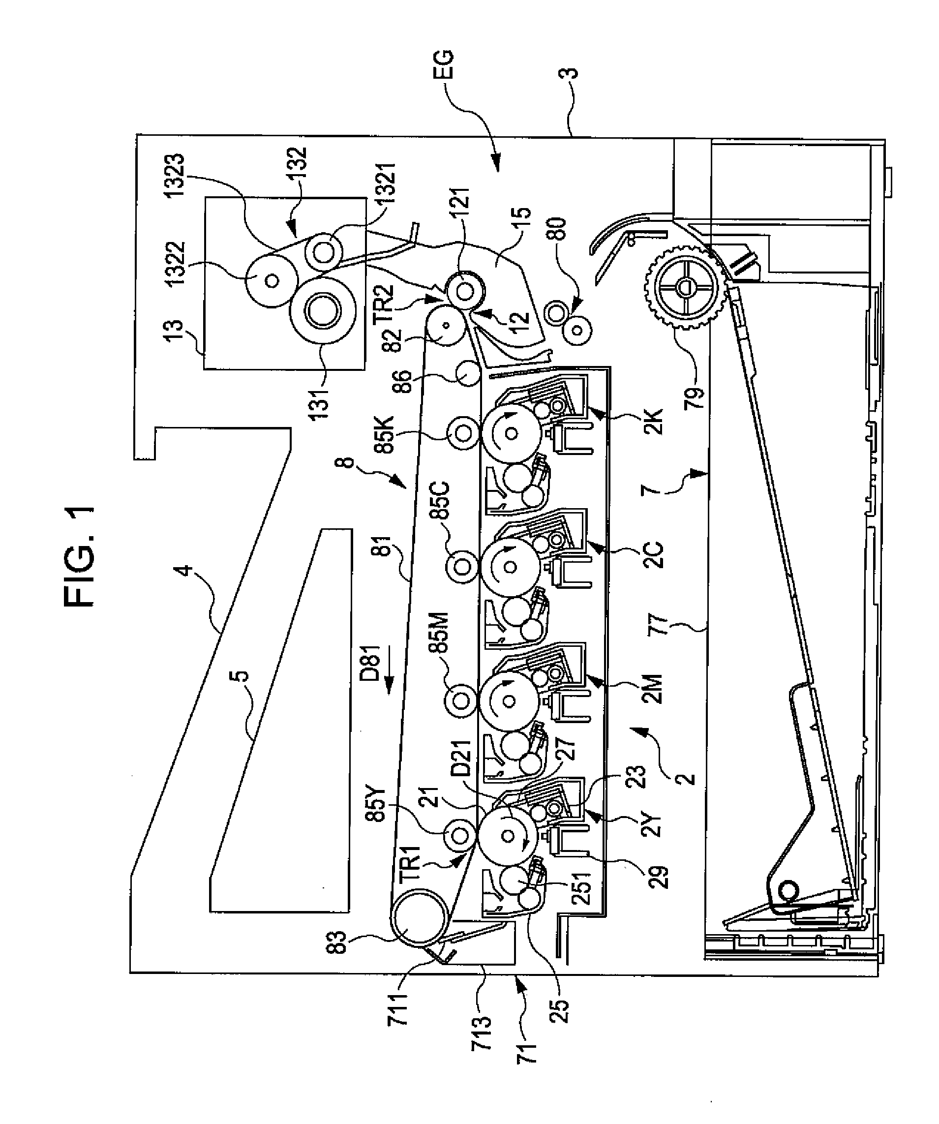
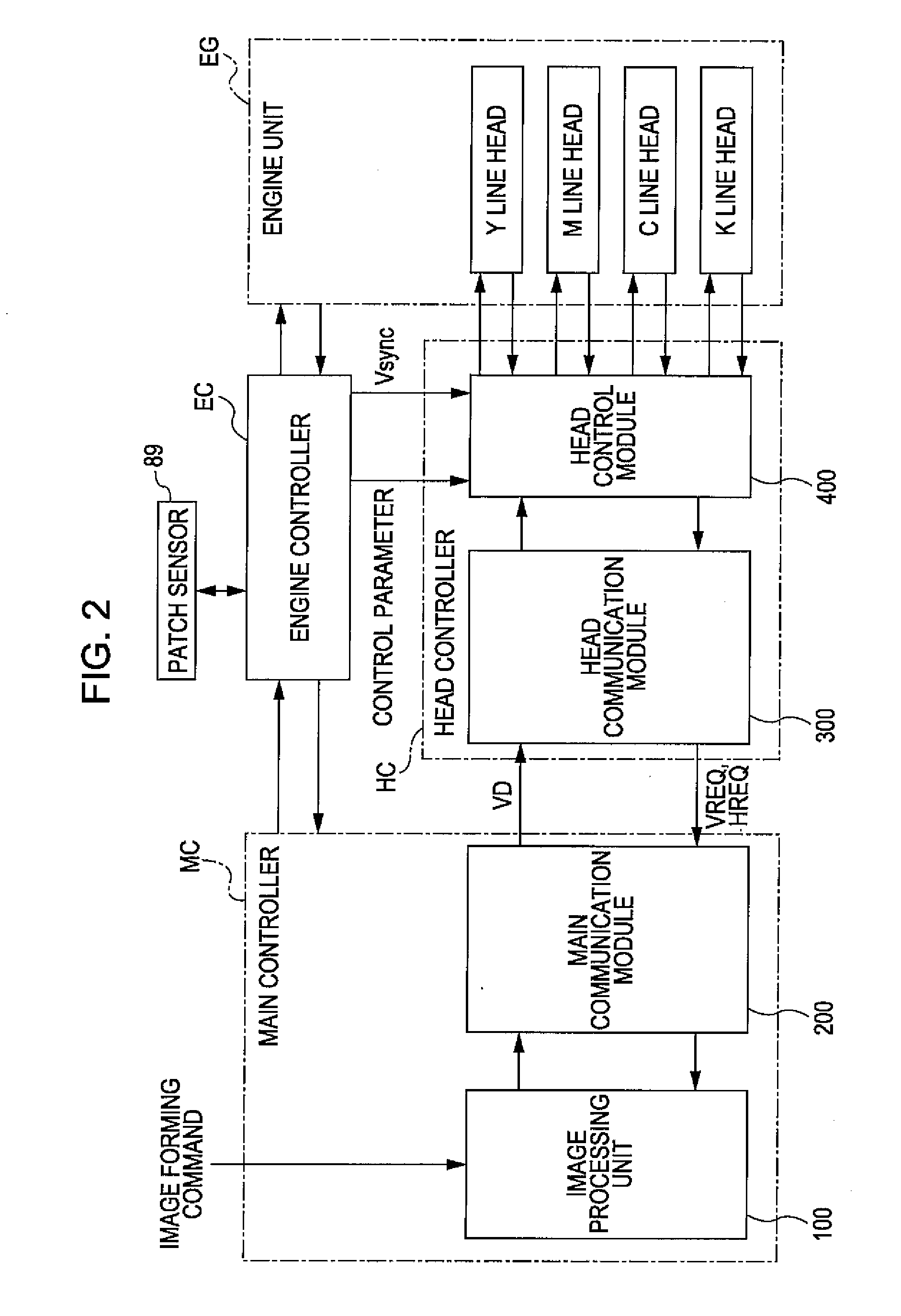
[0028]FIG. 1 is a view illustrating an image forming device according to an embodiment of the invention. FIG. 2 is a view illustrating an electrical structure of the image forming device of FIG. 1. The image forming device selectively performs a color mode in which a color image is formed by layering four colors of toner including yellow Y, magenta M, cyan C, and black K in an overlapping manner, and a monochrome mode in which a monochrome image is formed with only a single color of toner, a black color toner K. In the image forming device, when an image forming command is given to a main controller MC having a CPU and a memory using an external device such as a host computer, the main controller MC sends a control signal to an engine controller EC and the engine controller EC performs a predetermined image forming operation by controlling each of the parts of the image forming device, such as an engine unit EG and a head controller HC of the device on the basis of the control signa...


PUM


Abstract

An exposure head includes a substrate through which light from light-emitting elements provided on a first surface of the substrate penetrates from the first surface to a second surface. A rod lens array is provided on the second surface of the substrate to image the light from the second surface. A light transparent member is provided between the substrate and the rod lens array and fixed to the second surface of the substrate and the rod lens array. A support member supports the first surface of the substrate.

Description

CROSS-REFERENCE TO RELATED APPLICATIONS[0001]This application claims the benefit of priority under 35 USC 119 of Japanese patent application no. 2008-259369, filed on Oct. 6, 2008, which is incorporated herein by reference.BACKGROUND[0002]1. Technical Field[0003]The present invention relates to an exposure head that images light from light-emitting elements onto a rod lens array and exposes an object surface, and an image forming device using the exposure head.[0004]2. Related Art[0005]JP-A-2006-231649 discloses an example of such an exposure head in which light from light-emitting elements formed on a glass substrate is imaged onto a rod lens array that faces the glass substrate. In the exposure head disclosed in JP-A-2006-231649, the light-emitting elements are provided on a back surface of the glass substrate, where the back surface is disposed on the opposite side of the rod lens array, out of a front surface and the back surface of the glass substrate. Accordingly, light from t...

Claims


Application Information

Patent Timeline
IPC IPC(8): G03G15/04
CPCG03G15/326G03G15/04072G03G2215/0412
Inventor INOUE, NOZOMUARAI, YOSHIOTSUJINO, KIYOSHI
Owner SEIKO EPSON CORP
Why Eureka
Try Eureka