
Air-conditioning apparatus

a technology of air conditioning and air intake, which is applied in the direction of transportation and packaging, vehicle heating/cooling devices, mining structures, etc., can solve the problems of inability to adjust both the direction and flow speed of passengers sitting in the center and rear seats, and achieve the effect of reducing the change in speed and volume of supplied air

Inactive Publication Date: 2005-08-23
MITSUBISHI HEAVY IND LTD
View PDF15 Cites 8 Cited by
  • Summary
  • Abstract
  • Description
  • Claims
  • Application Information

AI Technical Summary

Benefits of technology

[0010]It is therefore an object of the present invention to provide an air-conditioning apparatus that minimizes the change in the speed and volume of supplied air when the direction of air blown from a vent is changed.
[0011]To achieve the above-mentioned object, the present invention provides an air-conditioning apparatus comprising an air supply duct for supplying air and at least one vent communicating with the air supply duct for blowing the air into a compartment of the vehicle. The direction of the air blown from the vent being adjustable, and the air supply duct including at least one branch chamber for reducing flow speed of the air flowing through the air supply duct so that the speed-reduced air in the branch chamber is blown from the vent.
[0012]In this air-conditioning apparatus, air is supplied through the air supply duct. The flow speed of the air flowing through the air supply duct is reduced in the branch chamber included in the air supply duct. This eliminates the directionality of the flow of the speed-reduced air in the branch chamber. When the air deprived of directionality is blown from the vent, the air is blown at an equal blowing speed and volume irrespective of direction. Consequently, the variation of the speed and volume of the air stream or the air is small when the blowing direction thereof is changed.
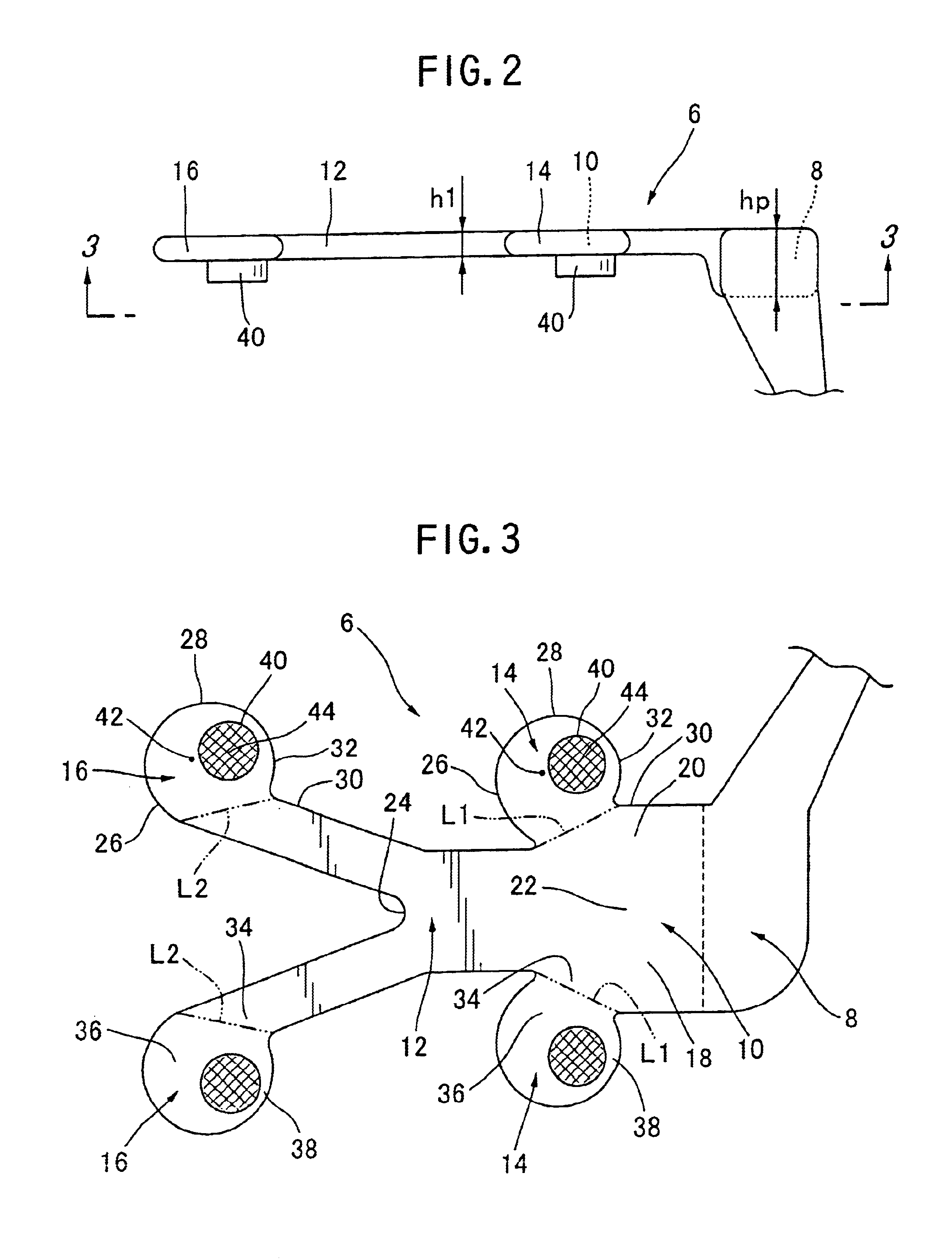
[0014]In this air-conditioning apparatus, the air flowing in the air supply duct is guided into the branch chamber by the front wall and the flow direction of the guided air is gradually changed by the curved surface of the front wall of the branch chamber to allow the flow speed thereof to be reduced. Thus, the kinetic energy of the air guided into the branch chamber is converted into pressure energy at a small loss. The inventors found that the branch chamber has a stagnating point located behind the centroid thereof where the pressure energy becomes maximum, that is, where influence of the flow speed of the air flowing from the rear to the front through the air supply duct of the vehicle V becomes minimum. Since the vent is communicated with the branch chamber at the stagnating point, the air deprived of directionality is blown from the vent so that the variation of the speed and volume of the air is small when the direction thereof is changed.
[0016]In this air-conditioning apparatus, a vent can be provided at each seat so that the variation of the speed and volume of the air is small when the blowing direction thereof is changed.
[0018]This air-conditioning apparatus offers the advantage that air can be blown toward the center and rear seats of the vehicle and the limited space in the vehicle can be utilized effectively.

Problems solved by technology

Therefore, there is a problem in that passengers sitting in the center and rear seats are not able to adjust both the direction and the flow speed and volume of the cool air stream at the same time.

Method used


Image

  • Air-conditioning apparatus
  • Air-conditioning apparatus
  • Air-conditioning apparatus

Examples


Embodiment Construction

[0033]An air-conditioning apparatus that is an embodiment of the present invention will now be explained with reference to the drawings. In order to simplify the explanation, only an air-conditioning apparatus from which a cool air stream is blown will be explained.

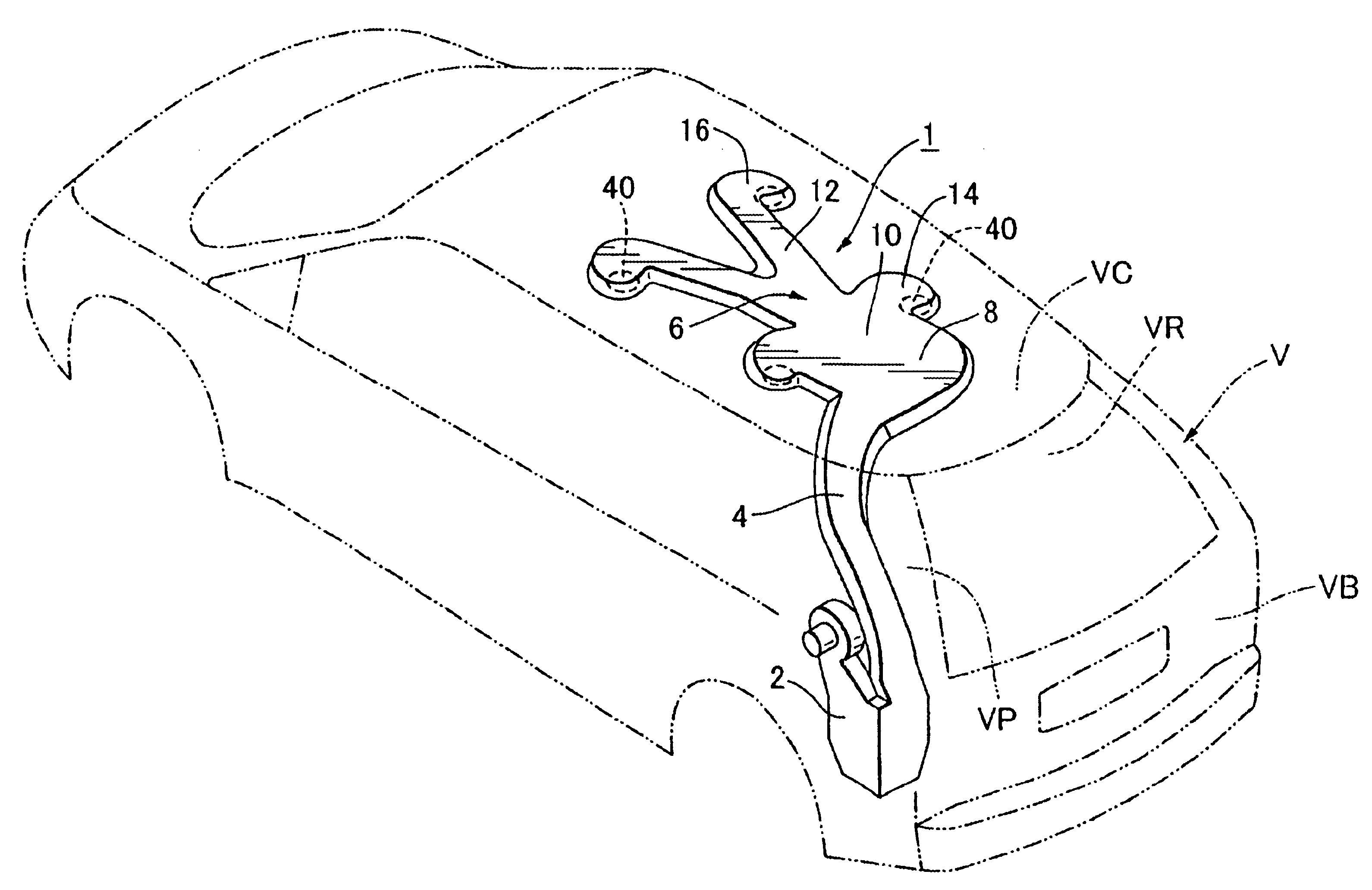
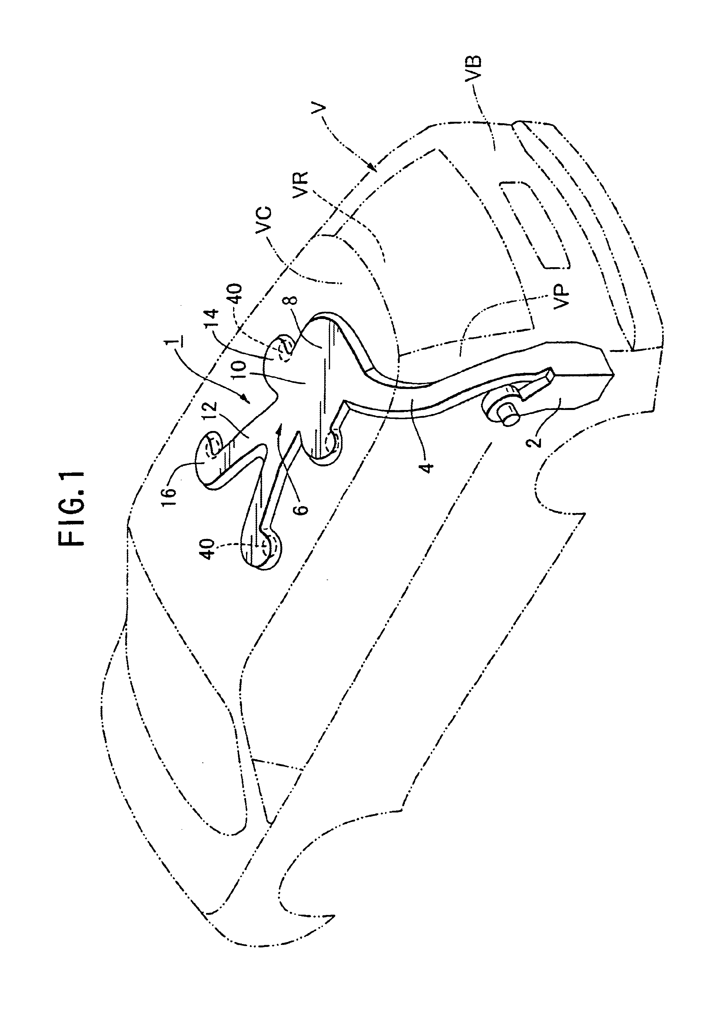
[0034]FIG. 1 is a perspective view of an air-conditioning apparatus of an embodiment according to the present invention. The air-conditioning apparatus 1 is provided with a cool-air stream supply device 2 disposed at the rear VB of a vehicle V, a pillar duct 4 connected to the supply device 2 and extending along a rear pillar VP to a ceiling VC of the vehicle V and a ceiling duct 6 connected to the pillar duct 4 and extending along the ceiling VC of the vehicle V.

[0035]The ceiling duct 6 includes a chamber 8 disposed in the rear VB and extending in a width direction of the vehicle, a rear main flow passage 10 extending forward with respect to the vehicle from the chamber 8, a front main flow passage 12 connected to the re...


PUM


Abstract

An air-conditioning apparatus 1 for a vehicle has an air supply duct 6 for supplying air and a vent 40 communicating with the air supply duct 6 for blowing the air into a compartment of the vehicle. The direction of the air blown from the vent 40 is adjustable. The air supply duct 6 includes a branch chamber 14, 16 for reducing flow speed of the air flowing through the air supply duct 6 so that the speed-reduced air in the branch chamber 14, 16 is blown from the vent 40.

Description

REFERENCE TO RELATED APPLICATION[0001]This is a continuation of International Patent Application No. PCT / JP02 / 07450, filed Jul. 23, 2002.BACKGROUND OF THE INVENTION[0002]1. Field of the Invention[0003]The present invention relates to an air-conditioning apparatus and in particular to an air-conditioning apparatus for a vehicle.[0004]2. Description of the Related Art[0005]The increasing popularity of sports utility vehicles (SUVs), which are substantially longer than ordinary passenger cars, has led to the installation in SUVs of air-conditioning apparatuses for supplying air, a stream of cool air for example, to the center and rear seats of the SUV, that is, to the second and third row of seats.[0006]FIG. 4 is a perspective view showing an example of such an air-conditioning apparatus. As shown in FIG. 4, an air-conditioning apparatus 50 has a ceiling duct 52 provided on a ceiling VC of a vehicle V for supplying conditioned-air, for example, a stream of cool air, and four vent grill...

Claims


Application Information

Patent Timeline
Patent Type & Authority Patents(United States)
IPC IPC(8): B60H1/00B60H1/24
CPCB60H1/00564B60H1/247B60H1/243B60H1/245
Inventor NAKAGAWA, NOBUYATOMINAGA, TETSUOIZUMI, HAJIMEKONDO, TOSHIHISA
Owner MITSUBISHI HEAVY IND LTD
Learn More