
Apparatus for severing the link between two sausages

a technology of severing the link and sausage, which is applied in the direction of sausage skin tying apparatus, butchering, linked sausage separation, etc., can solve the problems of unsatisfactory determination of twisting points, unsuitable for precise control of cutting operation at the desired high speed, and still carried out by hand

Inactive Publication Date: 2005-08-23
STIMPFL & GIESELER SONDERMASCHEN F LEBENSMITTELIND
View PDF15 Cites 8 Cited by
  • Summary
  • Abstract
  • Description
  • Claims
  • Application Information

AI Technical Summary

Benefits of technology

[0012]The choice of two sleeves which can slide into one another, with an internal diameter of one sleeve being slightly larger than an external diameter of the other sleeve, has the advantage of providing very good guidance for the cutting device. Furthermore, the two sleeves, during the cutting operation, form a closed space in which the remainder of the twisting point, if appropriate together with the clip, which has been detached is received.
[0016]To allow the sleeve to move with respect to the stripper, a square, which rests in a guide slot in a lateral surface of the sleeve, is formed integrally on the sleeve. The square simultaneously has the advantage of forming two lateral sliding surfaces for the sleeve, so that the sleeve cannot move out of its movement axis.

Problems solved by technology

Today this is still carried out, at great expense, by hand.
This detection system operates using a light barrier and mirrors and is therefore unsuitable for precise control of the cutting operation at the desired high speeds.
A light barrier of this nature is extremely sensitive to extraneous light, and the mirrors are subject to contamination, so that the determination of twisting points is extremely unsatisfactory.
This alone renders known devices unsuitable.
In addition, the cutting device itself, which is designed as a lifting blade, has proven entirely unsuitable for the speeds which are required nowadays.
The device is dubious in safety terms, since it has a valve shut-off system which always returns to the starting position even in the event of a fault.
In this case too, mirrors are used, and these can easily become contaminated or coated with a film of grease from the sausages.
The blade and its drive are entirely unsuitable for the high working rate of a sausage-cutting machine which is required nowadays.
These tail sections together with clips are extremely unaesthetic and are not desired by the customer.

Method used


Image

  • Apparatus for severing the link between two sausages
  • Apparatus for severing the link between two sausages
  • Apparatus for severing the link between two sausages

Examples


Embodiment Construction

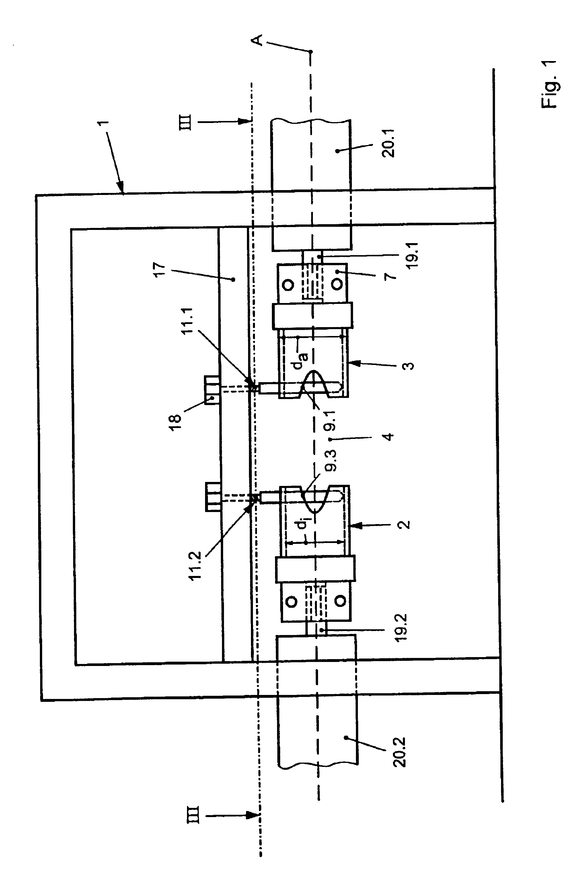
[0026]In accordance with FIGS. 1 and 2, two cutting devices 2 and 3 are located at a frame 1. These cutting devices 2 and 3 between them leave clear a space 4, through which a string of sausages (not shown in more detail) can be guided. This string of sausages comprises a large number of individual sausages which are separated from one another by a twisting point. If appropriate, one or more clips, which are generally made from metal, may be located at this twisting point.

[0027]As can be seen in particular from FIGS. 4 and 5, each cutting device has a sleeve 5 which is delimited at the back by a sleeve base 6. The sleeve base 6 is adjoined by a connection piece 7.

[0028]On the opposite side, the sleeve 5 forms a free, open annular edge 8, into which two cutting edges 9.1 and 9.2 are formed opposite one another. The cutting edges 9.1 and 9.2 are formed in the shape of a hollow and are sharp-edged in the region of this hollow-like formation.

[0029]Furthermore, a slot 10, in which a stri...


PUM


Abstract

In an apparatus for severing a link between two sausages, in particular for cutting out a clip at a twisting point by means of a cutting device which has a cutting edge, comprises at least two cutting edges lying opposite one another and movable toward one another when the twisting point is located between them.

Description

BACKGROUND OF THE INVENTION[0001]The invention relates to an apparatus for severing the link between two sausages, in particular for cutting out a clip at a twisting point, by means of a cutting device which has a cutting edge.[0002]Nowadays, sausages are produced by filling a skin, whether this be a natural or synthetic skin, with a suitable sausage filling in sausage portions. The individual sausages are separated between the individual portions, usually by fitting clips and / or twisting the skin, for which reason this point is also known as the twisting point. The result is a string of sausages, from which these sausages subsequently have to be cut off, for example in order to automatically package a certain number of sausages. Today this is still carried out, at great expense, by hand.[0003]DD 106 131 has disclosed a device for separating individual sausages from a string of sausages, which device comprises two part conveyor systems, each with a pair of conveyor belts. If a twist...

Claims


Application Information

Patent Timeline
IPC IPC(8): A22C11/12A22C11/00
CPCA22C11/006A22C11/12A22C11/125
Inventor STIMPFL, CHRISTOPH
Owner STIMPFL & GIESELER SONDERMASCHEN F LEBENSMITTELIND
Learn More